Zenfox T3 Triple channel dash cams free test invitation, limited quantity

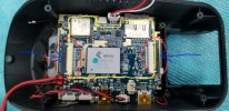
If you look at that silver thing, you can also see it is a woven material, and NOT a ribbon cable

If you google with "EMI shield fabric" you will pretty much find this stuff, albeit in various shapes

It looks like the ribbon is wrapped in the shield fabric is my point. Anyway, how the hell do I dismount the EMI shield? And if anyone looks at my photos, there is white thermal paste all over the EMI Shield Fabric and a Black Wire (Ground?).
 
No a CPU are a entirely different beast. :)
 
No a CPU are a entirely different beast. :)

Processor / CPU. Not sure there's really a discernible difference here.

Back to my original questions...Guess if no one wants to answer them, I give up.

1. That Fabric Tape looks like it is insulating the actual ribbon for the Front Camera to Rear Camera connecion.

2. How do you dislodge the EMI Shield from the Mainboard?

3. Why is there thermal paste all over the sides and black connector

4. Is there any way to dismount the heatsink from the shield and Fabric Tape
 
Okay.
I assume the ribbon cable could arc up and into the EMI tape to cover it for some part of the way.
Would be interesting if we could see how @EGS camera units with his ribbon cable attached look, could be where he cut the EMI tape was just before the ribbon cable get wrapped up, if so there should be that EMI tape left on his ribbon cable.
And since the EMI tape look as if it is glued to the back if the camera unit, thats probably whu he have not disconnected there, as it must after all have a similar connector there as on the main PCB.
 
Of course they are ribbon cables, the lens units need to be connected to the processor!

Yours will look the same inside as EGS's, so unless you have a plan for how to improve it, taking it apart when you don't understand the difference between ribbon cable and tape is a bad idea!

Look on page 49 with @EGS images.

1. How do I dismount the EMI Shield from the PCB / Mainboard

2. The Ribbon looks insulated in the Fabric Tape. So what exactly did @EGS do in his photos. As that ribbon is no longer present.

3. It does appear he removed his interior Camera. But how did he get the ribbon / tape from under the heatsink?
 
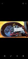
Yellow outline represents the area where the metal lid cover sits
Red oval marks are where each camera ribbon connects to
Blue arrows shows the black tabs that MUST be lifted carefully before you decide pulling those ribbons out. Doing it wrong could damage the ribbon or even worse the port itself.
You need to unwrap the EMI shield tape ( the one is making a bridge under the heatsink) from the ribbons going to the ports. No knifes or sharp objects should be used or any metal pry tools. remember the capacitors are still connected.
On the top left corner of the yellow line box, there is a dot of solder that grounds the lid and the pcb together and MUST desoldered before attempting to lift it open. So you better have a soldering iron if you wish to proceed.
I wish i could be clearer with this ...

Screenshot_20200704-205324_Gallery.jpg
 
Yellow outline represents the area where the metal lid cover sits
Red oval marks are where each camera ribbon connects to
Blue arrows shows the black tabs that MUST be lifted carefully before you decide pulling those ribbons out. Doing it wrong could damage the ribbon or even worse the port itself.
You need to unwrap the EMI shield tape ( the one is making a bridge under the heatsink) from the ribbons going to the ports. No knifes or sharp objects should be used or any metal pry tools. remember the capacitors are still connected.
On the top left corner of the yellow line box, there is a dot of solder that grounds the lid and the pcb together and MUST desoldered before attempting to lift it open. So you better have a soldering iron if you wish to proceed.
I wish i could be clearer with this ...

View attachment 52515

Thank you for humoring me here. I have zero experience prying open cameras.

1. So does the fabric tape come off before dislodging the emi shield? I have to unwrap the tape and then remove the ribbon from the board? Or am I confused and the EMI shield comes off first, then you remove tape and ribbon?

2. So is the EMI shield soldered to the board on the top left yellow dot?
 
Last edited:
Thank you for humoring me here. I have zero experience prying open cameras.

1. So does the fabric tape come off before dislodging the emi shield? I have to unwrap the tape and then remove the ribbon from the board? Or am I confused and the EMI shield comes off first, then you remove tape and ribbon?

2. So is the EMI shield soldered to the board on the top left yellow dot?

1. Unwrap the tape first
2. Unsolder the corner. You can use desolder wick to make it easier and cleaner.
3. Proceed to lift the lid from one side with a nylon pry tool. It will detach fairly easy.
4. Once the block has been pulled, then you can carefully pry up the black tabs to release the ribbons to each camera.
5. Let the fun begin! :) ;)
 
Thank you for humoring me here. I have zero experience prying open cameras.
No problem. I don't have that much experience in cooling systems but I find it a good opportunity to learn more about it. I frequently do tv repairs to a component level repair, replacing led strips, NAND chips (eprom), fet transistors, bulged capacitors, you name it. So I have some experience with this things and always willing to learn more.
 
Last edited:
No problem. I don't have that much experience in cooling systems but I find it a good opportunity to learn more about it. I frequently do tv repairs to a component level repair, replacing led strips, NAND chips (e-prom), fet transistors, bulged capacitors, you name it. So I have some experience with this things and always willing to learn more.

I can build computers, open laptops, etc. Far as working on boards, replacing capacitors, etc I'm way above my knowledge base. So 100% newbie here when looking at the camera and dealing with the pcb board.

Where exactly on your image is the emi shield soldered to the board? Is it on the top left hand side of the yellow line where they cross and make a T Shape in your diagram?
I had to go back to my older pictures.
It is where the yellow circle is. Hopefully it is the only point on yours. Mine had only one at that corner.
Screenshot_20200705-125926_Gallery.jpg
 
I had to go back to my older pictures.
It is where the yellow circle is. Hopefully it is the only point on yours. Mine had only one at that corner.

Perfect. For the moment I threw my camera back together. If ZenFox doesn't come back with any solution, I'll take a crack (hopefully not literally) at buying a thin piece of copper and sticking it under the EMI shield and over the CPU with Artic Silver. Or if anyone is curious to give that a try and report back.

FYI: Quality control SUCKS on these things. If you look at my photo, my Wifi Antenna is gooped in thermal paste. I don't see that issue on yours. Nor did I see thermal paste oozing out the sides per my other photos.
On mine the white stuff is like epoxy paste as it is very hard glue ans I can see they used plenty on yours and not enough on mine.
I wont be working on mine until I figure exactly the path I want to follow with materials. For example the copper plate and thermal compound.
 
FYI: Quality control SUCKS on these things. If you look at my photo, my Wifi Antenna is gooped in thermal paste. I don't see that issue on yours. Nor did I see thermal paste oozing out the sides per my other photos.
That is not really a problem, makes it less likely to for the connector to accidentally come undone :)
 
Yes securing some things, with a dab of hot glue are nothing new.
 
That is not really a problem, makes it less likely to for the connector to accidentally come undone :)

Can we say overkill? I mean whatever epoxy they used, that heatsink is fused to the emi shield. There's no way in hell that's coming off. Making the only possibly modification being placing a copper plate between emi shield and processor.
 
On mine the white stuff is like epoxy paste as it is very hard glue ans I can see they used plenty on yours and not enough on mine.
I wont be working on mine until I figure exactly the path I want to follow with materials. For example the copper plate and thermal compound.

Mine isn't ever coming off, put it that way. I guess it isn't a paste but some sort of hard epoxy. None the less, I think a copper plate will be the ONLY thing that can be attempted. I don't see separating the Heatsink and EMI shield being possible.
 
Since it's been unequivocally proven that the T3 does have a heating issue and as a result starts dropping channels. All these DIY suggestions are fine but now it's for Zenfox to address the highlighted flaws/issues.
 
Back
Top