Uninterruptible power supply using 5V power bank

That's a good explanation. But they could design a power bank with charging circuitry to get around the problem. I.e. when a device is connected to the power bank output while it is being charged, have that device powered by the feed into the power bank rather than the PB battery. If there is sufficient power to charge the battery on top, then do so. Since there is nothing connected to the battery output, it's OK, the intelligent charging algorithm will work.
It's not hugely difficult, but the market is competitive, and cost is more important than this feature. So I doubt we'll get it. Unless we do it ourselves external to the power bank ... which we are getting close to with the above circuits.

There are power banks like that, for example at least one of the GoalZero units.
 
I've been driving with my DIY uninterruptible power supply for my Xiaomi YI for quite some time now. Even though the solution seemed so obvious and easy for me, I found it's a rather big problem for dashcam owners (people go crazy with 12V batteries, ridiculously expensive BlackVue power packs, etc.)
I've put a nice write-up in here http://blog.nagimov.com/uninterruptible-5v-usb-power-supply/

It's based on 5V power bank (the same people use for charging their phones on the go) and couple of 5V relays. Cost of all the components (excluding the power bank) is around $20

Here's a picture with my layout:

very interesting setup and thread guys!

i have been wondering with this recently. My idea is to have a portable jump starter with 18A to 21A of capacity and 800A peak, with USB and 12V outputs.
the jump started is lithium based and, to get more peace of mind in case i am the one in a million cases where these batteries blow up with high temperatures, I am going to place it inside 2 (!) lipo safe bags:
https://www.amazon.com/gp/B07521JTLPhttps://www.amazon.com/gp/B0719H46PF
i'm totally out of electronics and DYI gadgets but the ideas here are very up to the point.

however, a friend of mine asked me a simple question that somewhat baffled me: why not just hard-wiring the cams to the car's battery?
I know that many people use this solution and complement it with a circuit switch when the battery's voltage gets down under a certain level (12.XX V), like Blackvue's Power Magic Pro or VicoVation's Vico-Power Plus, but i don't like to mess with the fuse panel and I a assumed that the car's battery will not be able to power 4 dash cams in parking mode (Blackvue DR750S-2CH and Thinkware F800 Pro-2CH). Also, i'm not even sure if my new car will have the fuse panel inside the car or the battery's specification (only that it is an AGM with at least 850 CCA, so I guess it will output more than 100Wh).

So i cannot say how much time will the battery be able to power 4 cams, that will request about 6Wh or 500mAh in parking mode, before reaching the safeguard threshold (12.2V?) so to not damage the battery.

Anyway, i just have the intuition that this is not the way to go. the way to go is to have a separate power source for the Dash cams and use the car's battery only when running and to charge also the separate power source.

But the market solutions for this are way too expensive, even ludicrous: Blackvue's Power Magic Battery, Cellink B, ...

So what you guys have to say about a secondary battery solution vs hardwire solution? And how long can a car's battery power up a setup like this one?

And if go for a DIY solution like the ones in this thread i also have a small problem with BlackVue since it is powered by a cigarette light socket and needs a 12V input, and the solutions here use USB 5V (for Thinkware there is no problem)? Is there an adapter for converting a 5V to 12V?

Thanks!
 
In my experience with what would be a huge battery for a car, 1-2 hours with 4 cams might be OK, but any longer will shorten your car batteries life considerably. And even this may be excessive for small batteries. You definitely need outside power for 4 cams.

Phil
 
In my experience with what would be a huge battery for a car, 1-2 hours with 4 cams might be OK, but any longer will shorten your car batteries life considerably. And even this may be excessive for small batteries. You definitely need outside power for 4 cams.
Phil

Thanks Phil!

Out of curiosity, I could not find yet the math on how to get the threshold value of, say, 12.2V, from a pre-known power consumption rate. If the battery has 12.8V and is capable of providing 100Wh, draining 0.5A from it how long will it take to reach 12.2V?

I guess that I could make this:
100Wh/12.8V = 8.33Ah
12.8V-12.2V = 0.6V
and then maybe there is a discharge rate curve that defines how voltage decreases with time (?)...

from a static and simplistic point of view, draining ALL the battery at 0.5A: 8.33/0.5 = 16.7h.
since i'm only interested in "discharging" 0.6V then 8.33Ah*0.6V / 12.8V = 0.39Ah. So, the battery threshold would be hit in less than 1 hour powering 4 cams if they are "awaking" frequently.

The OP's solutions is fascinating. It seems simple and @Rajagra reservations didn't seem to be confirmed and OP put a small video of the running solution. Any safety issues in this solution that might come up?

It's crazy how no one has implemented a commercial solutions like this :O

But i have an issue: how to power up 4 cams? this solution only has one 5V output. How to extend this to two 5V outputs? (and in the case of BlackVue, it needs to be 12V...)
 
I can only offer my personal observations- I haven't "done the math". When I first got into dashcams, the almost complete consensus was that powering a cam overnight was going to greatly reduce the life of my battery, and that a BDP was mandatory to stop the cam before damage occurred. Partly by my forgetfulness with unplugging my cam when getting home at the end of the day, and partly by design I decided that I'd chance running my Mobius continuously- no problem. Then I tried other cams. Then I tried 2 cams, then 4 when I was parked in bad neighborhoods at work, and then overnight. This is an old full-size American Ford van, much more battery than anything you normally find in cars today. I'm very "in touch" with it and I can tell if the starter is turning over the engine with even slightly less vigor than it should. Years of automotive experience tells me that when this is noticeable, your battery voltage is getting too low. So that's what I go by- maybe I'll document it with a voltmeter some time in the future- but it's definitely lower than you should risk. My current dual-channel cam leaves me a no-start after about 36 hours; definite battery damage going this far. Overnight is pushing it. "Doing the math" is only part of the picture anyway; an older battery will have less tolerance for abuse and less power reserve to use so today's safe solution might not be so good next year.

You might do OK with one cam parked overnight, you should be OK for 8 hours except in really cold weather (which I don't see here). You'd think that 2 cams would be the same for half that time, but the higher current draw damages the battery more quickly so you don't get that much. Worse for 4 cams. Even with my 'ideal' car battery, 4 cams at 2 hours is pushing it hard. Since I have individual cams, my present solution is to leave on only the one(s) I think necessary, as I need a power upgrade too if I want to do more. 4 cams overnight is do-able, just not easy.

Many here use powerbanks- I don't- so that is a subject I'll leave to others with more experience for specific recommendations, but in general that's probably your best route for the 5V cams. I know some good ones have 2 USB outlets. For the 12V one, perhaps a "jump-start" device could be used, or an AGM or SLA battery (I just used an SLA for a temporary cam install) These are safe technologies but much larger than a powerbank and you'll have to do your own engineering with these. I think 12V powerbanks are made so that may be an option. IMHO the 'perfect' solution would be a battery isolater and a wet-cell deep-cycle 12V battery (or two) like RV's have. Lots of space needed, lots of heavy wiring needed, expensive, and a safety issue or two to consider. Pretty simple to do though. It's my own plan when I can get the extra cash to implement it.

So there are a few ways to get what you want, and you should first decide which way you'll go, but IMHO the best way is to run as few cams as possible, as that makes the job immensely easier however you go about it.

Phil
 
The reason of using double channel relay board instead of one DPDT relay is simply the cost and simplicity of assembly :)

Ok, i have read this thread again to understand better what is being done here as i'm a totally noob to this DIY stuff, specially when it involves electronics/electricity, and I envy people that can actually do this stuff.

but I don't understand your option as I'm still trying to figure out how this hardware works.
a double channel relay board is an SPDT? or two SPST?
the cost of a DPDT is about 50% more than of the 2 channel relay but you also mentioned simplicity in the assembly. how come? reading what @SawMaster wrote, a DPDT would do the same work and I would guess that a more direct hardware match for this job would mean a simpler assembly :unsure:

also, am i correct to assume that for powering two cams it is best to build two systems like this and just use another USB output from the power bank and share the car's battery power when it is on thru the 12V cigar lighter and an USB splitter?
 
You can "pigtail" the power output of a powerbank into as many branches as you like, so one powerbank could power all your cams. It's the charging input to the powerbank which needs special care in handling, and it cannot be tied into anything else. Do a search for "2 port USB hub" on your favorite internet store site and you'll see lots of options.

If there is an issue with using one powerbank it would be capacity, which would need to be large enough to get the runtimes you want. Large capacity powerbanks take longer to fully charge than smaller ones, so this might be important to consider too. Your needing 12V for the Blackvue means that it is going to need to be dealt with seperately, but for shorter runtimes (say 6-8 hours) your car battery should be able to handle it. Your original idea of a jump-pack with USB and 12V outlets could consolidate everything making things easy, but you've still got to charge it somehow and with me not knowing how it's charging system functions I can't say whether it would be appropriate to use it as a "pass through" device.


I feel that I have something new to add to this general discussion based on my recent usage of an SLA battery to power a temporary cam set-up
. When my little battery became depleted, the G1W/HC it was powering shut down as expected, but then began to attempt to re-boot repeatedly, shutting off before that process could be completed due to inadequate power input. It doesn't appear to have had any adverse effect on my cam, card, or files saved but I'm certain this is not optimum, and other cams may not fare so well in this situation. As I've done similarly when I forgot to turn my car-battery powered cams off overnight with my various cams (also without apparent ill effect) this may not be an issue but I'd like to hear other people's thoughts and experiences on this.

Phil
 
thank you Phil, very kind of you.

i will be using a jump starter. it is able to power devices and be used to jump start the car if needed. also, total capacity in mAh tends do be almost double of common power banks. i will be placing it inside two lipo safe bags. i believe if i get unlucky i stand a good chance of not having a fire make much damage to the car, for what i could see of testing examples on Youtube. i have several goo options, for what i've been able to tell all Chinese made unfortunately, but i guess this is standardized well enough that even if they build a bad product it will still offer some good reliability, as long as you do not go for an obscure/un-reviewed brand. they usually have 18000mAh to 21000mAh, offer one 12V/10A output (some offer also another 19V/3.5A) and at least 2 USB 5V outputs with 1A or 2.1A and even USB-C outputs with quick chargers.

the jump starters have no pass through as you well noticed. so the circuitry has to switch on power from car battery to jump starter when the ignition is on and have the cams get power from the car battery, and when the ignition is switched off, the power to the cams comes from the jump starter that has also is charging from the car's battery stopped. basically what has been done in this thread.

given that i will have a two set of dual channel cams i will need two power outputs. but to make things more complicated, one of the sets (the BlackVue one) needs a 12V/1A input source: DC Plug:(-)—C—(+) (Ø3.5 x Ø1.35). actually i just checked Thinkware and it also needs a 12V input... I was with the idea that it used a 5V input.

anyways, i discovered that there are step-up circuits that can receive 5V and transform to 12V output. Or i can simply use the examples here with a 12V circuit?

as you also mentioned, i can also have a splitter/hub for the cigar lighter or USB outputs. I am not sure however if these solutions are stable. i mean, they receive power from a source and then take the same power and output them at the same rate? 12V in and 12V out x2 or more outputs? i guess it is the same as power cord extensions...

since the two sets of dual channel cams (Blackvue and Thinkware) will work in tandem, then i guess i can just have one circuit designed as shown in this thread, but working on 12V, and having the output being feed to a 12V splitter/hub? maybe a dual cigar lighter port, and then just attach the cigar lighter sockets from the two sets to this.

having less wires and stripped wires would be a plus, so i still have to understand how this would work with a DPDT relay
 
How to power with a jump-start pack will depend on how it deals with charging. If it switches from car battery feeding it's outlets when it is being changed, then back to itself when the car is no longer charging it, then half the problem is solved and no relays will be needed. But I can't say if any particular jump-start pack functions this way; you will have to investigate this yourself for each one.

As to the 'step-up' devices, these are called "boost converters" and they tend to be somewhat inefficient electrically, so using them to convert 5V to 12V will involve some losses. Based on how these are built, you can expect from 70% to 90% efficiency, with some exceeding these figures. Our cam's 12V to 5V power supplies are known as "buck converters", and these are more efficient with figures of about 85% to 95+% being common. So if it were me, I'd aim for using a 12V auxillary power source (jump-start pack), then using a cam's PS or hardwire kit downstream if needed to get 5V. This will maximize efficiency, be easier to configure, and allow for one power source to feed all cams.

The 12V ciggie-socket output can be split, same as with 5V and powerbanks, so that you can have as many outlets as you need. As long as the total power being drawn does not exceed the capabilities of the jump-start pack's 12V output at it's ciggie socket all will be well. With our small power needs I don't see any problem here with any jump-start pack.

On jump-pack quality, I'd avoid anything cheap, as these might contain low quality LiIon cells and poorly designed charging circuits. LiIon (and to a slightly lesser degree LiPo and LiFePo) cells require a specific well regulated charging scheme. With LiIon (which most of these jump-packs use) you'll have several cells wired in series for output, and in charging each cell (or matched cell pair) has to be monitored, charged, and dealt with individually in the charging circuitry (which is how laptops and power-tool batteries are done). This adds cost, so some cheap multi-cell devices rely on only factory cell-matching for safety, and charge everything as a whole. Should any cell weaken faster than the others, it will receive more charge than it can handle which will cause it to overheat and fail (usually with flames) so best to avoid these. Look for wording which says the pack has balanced charging, and beware of any which set a time limit on how long the charger can be used- that is an almost certain sign of a cheaply made and unsafe charging system.

As to quality of the LiIon cells themselves, there is no way of knowing what you'll get, so here sticking with a well-known reputable brand name is your best protection. If the cells are made by Samsung, Panasonic, Sony, or LG then they are good, but fakes of these brands are known to exist. Good device manufacturers will use only reliable sources for these cells to avoid the fakes, and may switch among these brands during manufacturing runs due to cost or supply variations, so the brand of cell used is rarely if ever going to be mentioned. And teardowns from a different batch may reveal different cells. So all we've got to go on is the device manufacturer's reputation, which by sticking with only known good brands is usually good enough.

You may come across jump-packs which use other battery technologies such as NiMh or AGM. These can be safely used in a 'pass-through' manner as their charging is not as critical to safe operation. With these types, hook-up and use will be easiest but they will have considerably lower power levels available compared to LiIon. The older jump-packs were made this way before LiIon's became commonplace and relatively cheap. I would avoid these because of the far lower capacity and the fact that battery wear happens much more rapidly with these compared to LiIon types, but if they can provide the power you need they will work OK.

I wish I could recommend a specific jump-start pack for you but I have no personal experience with them, so that will have to be left to someone else. All I know on them is based on my knowledge of Lithium-type cells, batteries of all types, and their charging systems of which I feel I am qualified to speak about, as this is a particular hobby of mine which I have very well researched and worked with for many years now. I'm happy to help with what I can, so if you have further questions ask and I'll do my best to answer them, and if I don't know then someone else here might. The members here are a very helpful bunch, which makes being on DCT a more pleasant experience than being nearly any other place online.

Phil
 
Thank you Phil, you have been providing great help.

the jump stater is difficult to choose but i've select a few options that seem more reliable. the market is full of Chinese brands and sellers, and rarely there is technical data about the functioning of the jump starter, like what is the cell brand and what kind of protection circuits are used. and most reviews focus only if they work or not...

these jump starters have no pass through so i will need to implement a circuit similar to what has been done here by the OP with relays. but since both dual system cams use 12V inputs then i will need that the circuit works at 12V instead of 5V. this way i don't need any step-up converters.

i will try to figure out the difference to a DPDT solution also.

you mentioned that "As long as the total power being drawn does not exceed the capabilities of the jump-start pack's 12V output at it's ciggie socket all will be well". how can i know that? i believe jump starters just say the total capacity in mAh and the values in Voltage and Amps of their outputs. that is one thing that puzzles me. if an output says 12V/1A how can i split the feed to two sockets/outputs of 12V/1A each? and if the jump starter output cannot keep with the power requirements that means that it will only give a lower voltage and/or amperage to the load or that will mean also a stress placed to the jump starter (leading to overheat for instance)?
 
you mentioned that "As long as the total power being drawn does not exceed the capabilities of the jump-start pack's 12V output at it's ciggie socket all will be well". how can i know that?

If that spec isn't listed, ask the seller- they should have or be able to quickly get you the answer.

if an output says 12V/1A how can i split the feed to two sockets/outputs of 12V/1A each?

In short, you can't. You cannot draw more here in total than it can supply singly, however with most lighter-plug supplied devices requiring much higher amperage than we need here, I would be rather shocked to see a 1A limit on the socket as that would render it almost useless. It's not impossible, but I'd expect at least a 5A rating there and probably more, which will be enough for your purposes.

Phil
 
sorry, my bad. the outputs are always 12V/10A. some offer outputs also at 19V/3.5A
 
OK, so I made my first circuit! this is fun.

1543078469343.png

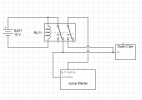
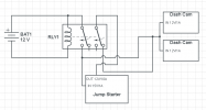
I decided to use a DPTP relay to make this UPS system working at 12V.

not sure why the OP used a Optocoupler with 2 channel relay. probably because it is used for building and connecting to other circuits? in this case I do not need to connect to anything else besides "solid" hardware like a jump starter and dash cams and no PCBs. i read that an optocoupler can some advantages in circuit isolation but i'm still not familiar with all this.

anyway, i have some doubts on this since i will be powering dash cams that need 12V/1A and a jump starter that has an imput of 15V/1A. also, i will have 2 dash cams (2 channel). so i need 15V+12V+12V ...
1) the relay needs a 12V power on the coil to activate it? since that power will come from the car battery via the cigar light socket how can i then pass that power also to the one of the COM pins in the relay? do i need to place a step-up circuit before the COM(1) ?
2) how can the DPDT provide the necessary voltage to the 3 loads? again, need to put some step-up circuits?
 
Looks like you've got it (y) It's the simplest circuit which gives this function. On the step-up (boost) for charging the Jump pack, I'm not certain it's really needed. When running, most cars have 13.8+ volts in the system and that should be sufficient. I'd try it like this before adding anything. I'd also recommend using an automotive-type relay as they are meant for 100% duty and should it ever need replacement, you can have another in your hands that same day anywhere in the world. You can usually source these with wired plugs which makes life much easier then trying to use individual connectors. Get one with a 15 amp or more rating just to be safe. The pin-out will be on the relay case with a similar schematic, or on the card the relay comes with. These switch pretty fast so I doubt you'll have any problems with spikes or drop-outs at the cams, but if you do a couple of caps can smooth that out. I would like to see you add fusing between your 12V+ source and also on the 12V+ output of the jump-pack for added safety. 3A or 5A should do OK for both. If you want to go OCD, add fuses for each cam at the cam manufacturer's recommended rating too. I wouldn't bother as the other two protect everything downstream from either power source.

As a note to others, this circuit should be used only where the jump-pack or another battery used in it's place has a charging regulator built in as there's nothing here regulating current flow into it. Wet cell and SLA battery types do not normally need this regulation but all Lithium battery types do. AFAIK all powerbanks use some form of Lithium battery technology so know what you are doing and be sure they have charging regulation built in before substituing one into this circuit. Also with other cell types, the fuse ratings I mentioned will need to be altered to fit the characteristics of the battery type and size being used.

This is exactly how I'm going to wire in the auxillary battery in my own car, except that I'll be drawing more power and using larger fuses and wiring to suit my needs.

Phil
 
had the connections wrong. NC and not NO

View attachment 43299
Normally it is not a good idea to connect the output of a powerbank (jump starter) to it's input, they are not very good at charging themselves, and certainly don't work like a perpetual motion machine...

Also, with lithium powerbanks you should normally switch both the + volts and 0 volts since the 0 volts output is not the same as the 0 volts input.

the jump starter doesn't have the input connected to the output... the circuits are isolated in the relay. but i probably need to put some ground connections in the circuit.

Looks like you've got it (y) It's the simplest circuit which gives this function. On the step-up (boost) for charging the Jump pack, I'm not certain it's really needed. When running, most cars have 13.8+ volts in the system and that should be sufficient. I'd try it like this before adding anything. I'd also recommend using an automotive-type relay as they are meant for 100% duty and should it ever need replacement, you can have another in your hands that same day anywhere in the world. You can usually source these with wired plugs which makes life much easier then trying to use individual connectors. Get one with a 15 amp or more rating just to be safe. The pin-out will be on the relay case with a similar schematic, or on the card the relay comes with. These switch pretty fast so I doubt you'll have any problems with spikes or drop-outs at the cams, but if you do a couple of caps can smooth that out. I would like to see you add fusing between your 12V+ source and also on the 12V+ output of the jump-pack for added safety. 3A or 5A should do OK for both. If you want to go OCD, add fuses for each cam at the cam manufacturer's recommended rating too. I wouldn't bother as the other two protect everything downstream from either power source.

As a note to others, this circuit should be used only where the jump-pack or another battery used in it's place has a charging regulator built in as there's nothing here regulating current flow into it. Wet cell and SLA battery types do not normally need this regulation but all Lithium battery types do. AFAIK all powerbanks use some form of Lithium battery technology so know what you are doing and be sure they have charging regulation built in before substituing one into this circuit. Also with other cell types, the fuse ratings I mentioned will need to be altered to fit the characteristics of the battery type and size being used.

This is exactly how I'm going to wire in the auxillary battery in my own car, except that I'll be drawing more power and using larger fuses and wiring to suit my needs.

Phil

thanks. i read that when running the cigar lighter socket on European car models (which is my case) can go to 14.5V. in any case i think also i will have no problem feeding the jump starter.

using fuses is a good idea. still not sure how this works but for what i have read it makes sense. a fuse, a diode, or something else at critical places.
i believe some relays have also a diode or resistor in the coil circuit to sustain the voltage spike when the electromagnetic field collapses when the coil is power down. so yeah, i am thinking on a DPTD automotive relay that are usually prepared with this stuff.
placing some capacitors is also my plan as i doubt this simple circuit will work with any problems. have to add at least one to keep power close to cams.
the relay by being mechanical can switch in a few milliseconds, 10ms or more which is just in the borderline to lead to power losses. an UPS typically switches at 10ms or less. so i might also consider a MOSFET but that is even more out of my comprehension at the moment.
 
You definitely want fusing, and it should be arranged to be as close as is practical to the source it receives power from. That offers the best protection. My experience has been with 5V cams only, but all mine will tolerate around 1/4 to 2/3 seconds of power dropout without stopping their recording or showing any glitches in the videos when viewed. Based on that I doubt that the relay switching speed will be an issue. As cheap as this is to build I'd try it as-is first, I honestly believe it will function just fine. I also don't believe you'll need caps to smooth the switching or moderate spikes, but in most relay circuits used with electronics in general they are commonly seen as it's a good practice. Some car-type relays have this built in but most don't. I don't believe this is indicated on the relay schematic so you'd have to pop the cover and look or get full specs on the relay you choose to know. ditto on the coil resistor. I've swapped the two types around in many cars for testing and repairs and never saw any anomalies.

A UPS for a computer does need fast and clean switching as they have no built-in supercaps or batteries like dashcams do to provide momentary power current and spike buffering. I don't think it will have any tangible benefits here even if it would be more ideal. I see no point in perfection when simplicity can do the job equally well and with fewer points of potential failure. In reality when a cam ispowered from a car, it's going to see some current spikes, low voltages, and high voltages often in rapid succession, yet I've not seen anyone complain about any of this save for stop-and-start cars and in some diesels which take a bit longer to start than most gasoline cars. It seems dashcams handle such power anomalies quite well.

Phil
 
yeah, you're right, i forgot that dash cams have supercaps. the idea of using capacitors close to cams is not only to handle current fluctuations but also to serve as a storage of energy in conjunction with step-up circuits.
i do not know yet how i will power two 12V cams with only one source.
I have one 12V output from the jump starter (there is one brand with two outputs) and one 12V output from the battery thru the cigar lighter.
when the car is on, battery will have to fed the relay coil, the jump starter and two (double) dash cams.
even when using the jump starter as power source when the car is off i still have to fed two 12V loads for the dash cams.

i've seen cigar lighter expansion sockets but i'm still not sure how they work. do they have step-up circuits so that they can take a 12V input and provide 2 or more 12V outputs?
 
Back
Top