Adding an ON/OFF switch for hard wired parking mode.

I think that I've found a simpler solution to my problem in this thread using a single pole dual throw switch:

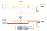
I've sketched up the schematic below.
Camera Parking Switch SPDT.jpg
Avoids the need for relays and issues with coil surge.
Using the switch while the camera is on will cause a momentary loss of power to the Batt terminal of the camera and cause it to restart (can a capacitor be used?)
 
In the end I've modified the Power Magic Pro I already had to achieve the same result. This keeps continuity of power to the camera when I change its switch from parking mode off to on while allowing the car's ignition to control parking mode. I can also use the camera's built-in voltage cut-off which has more fine tuned control than the PMP.

Schematic below.

1674282229316.png

I cut the accessory plug off the end of the PMP and connected the ground (black) and battery cables (yellow) from the camera's hardwire kit directly to the output ground (black) and power (red) from the PMP. I've then connected the battery (yellow) and ground (black) from the PMP to the car battery and ground respecitvely to provide the constant power for parking mode. Finally I've connected the accessory cables (red) from both the PMP and camera hardwire kit to the car's accessory circuit. It's important to connect the camera's ground cable to the PMP rather than direct to the car's chassis, as the switch in the PMP is located on the ground side of the circuit.
 
While reviewing the BlackVue DR900X-2CH dashcam, I mentioned I would like to have BlackVue include an on/off switch on the camera. In the testing video in that review series, I show my modification to the 3-wire harness that inserted a DPST switch to allow me to power down the dashcam when parked at home. I used a dual pole switch to cut off the constant and accessory power to the dashcam but I leave the ground wire connected all of the time. I cutoff constant and accessory power to be sure the dashcam has no power while parked. Since I review multiple dashcams, I also wanted a configuration that could be used with any dashcam that I might plug into the cable. Since there is a supercapacitor in the dashcam, it will power down gracefully when the power is removed by turning off the switch.

I show this modification in the "testing" video of my three video review series of the DR900X-2CH dashcam.

I also show that I extended the 3-wire cable by six feet since my test vehicle is a long wheel base ex-cop car and the main fuse panel and dashcam battery packs are located in the trunk of the car. To make this "easier" over the long term, I used the Molex connectors used by dashcam battery pack's output power port to add my extension and to put the DPST switch inline in the 3-wire cable. A bit overboard for the typical install, but nice to have so I can reconfigure my setup whenever I change dashcams in the vehicle.

Hi - why not just put an SPST inline on the ground connection and cut that? Is there something electrically bad about this approach compared to cutting the Hot and ACC legs with a DPST?
 
Hi - why not just put an SPST inline on the ground connection and cut that? Is there something electrically bad about this approach compared to cutting the Hot and ACC legs with a DPST?
Switching off the ground connection should work as well. I've always been one to stop supplying power to a circuit when it doesn't need it. That's the way the dash camera power is handled in its original form so I just continue doing that with any switch I put in place.
 
I think that I've found a simpler solution to my problem in this thread using a single pole dual throw switch:

I've sketched up the schematic below.
View attachment 63512
Avoids the need for relays and issues with coil surge.
Using the switch while the camera is on will cause a momentary loss of power to the Batt terminal of the camera and cause it to restart (can a capacitor be used?)

Hey thanks for the clear diagram. I've kicking around the idea of adding some IOT style automation to this setup.
Basically replace the SPDT with an Arduino Nano RP2040(can be powered by 5V), and a 3V relay. Combined with AutoArduino/Tasker, the hope is to have parking mode turn off when I get home, and turn on when I leave based on Tasker presence detection through my android phone.
Circuit logic is the hard part for me, wondering if you have any thoughts on whether this can be done with an NO/NC relay? If the relay is powered by the arduino, any issue with coil surge like you mentioned before?
The other thing I'm having a hard time thinking through - should the arduino be powered by an ACC circuit or an always on circuit?
I guess I should add I'm running a BBMC powercell 8 battery, so probably everything should be grounded to that rather than the car right?
 
Basically replace the SPDT with an Arduino Nano RP2040(can be powered by 5V), and a 3V relay. Combined with AutoArduino/Tasker, the hope is to have parking mode turn off when I get home, and turn on when I leave based on Tasker presence detection through my android phone.
I wonder how much power an Arduino would consume and whether it would significantly diminish your runtime from the BMC powercell battery? Also, the relay coil itself will draw power when it's engaged potentially drawing down the battery even quicker.
Circuit logic is the hard part for me, wondering if you have any thoughts on whether this can be done with an NO/NC relay? If the relay is powered by the arduino, any issue with coil surge like you mentioned before?
Unfortunately I don't have the knowledge to answer whether coil surge would be an issue for the Arduino. There are plenty of single channel relay boards available for the Arduino which are likely designed to limit the impacts of coil surge. See here for some information on how they work.
The other thing I'm having a hard time thinking through - should the arduino be powered by an ACC circuit or an always on circuit?
The Arduino would need to be powered by an always on circuit so that it can detect whether to turn parking mode on or off for a couple of reasons I can think of:
  • If it's connected to the ACC circuit, it may not detect the change in location and activate the relay in time
  • Assuming the default would be normally closed when parking mode is required so you didn't have the increased power consumption of both the camera and relay coil, and the relay activated to open when at home so you would only have the power consumption of the coil.
I guess I should add I'm running a BBMC powercell 8 battery, so probably everything should be grounded to that rather than the car right?
You need to ground the device to the power source it's running from. So if the camera and Arduino are running from the BBMC powercell battery then you need to ground it to that battery.
If you were running the Arduino from the car's battery, and the camera from the BBMC powercell, then the Arduino would need to be grounded to the car, and the camera to the BBMC powercell.

Personally I think that running the Arduino and relay in the way you're thinking will have a power draw that is too high, depleting your battery too quickly
 
Switching off the ground connection should work as well. I've always been one to stop supplying power to a circuit when it doesn't need it. That's the way the dash camera power is handled in its original form so I just continue doing that with any switch I put in place.
I have been wanting to put a switch in my system.. switching the ground seems like an excellent idea. Be interesting if anyone has done that.
 
I wonder how much power an Arduino would consume and whether it would significantly diminish your runtime from the BMC powercell battery? Also, the relay coil itself will draw power when it's engaged potentially drawing down the battery even quicker.

Unfortunately I don't have the knowledge to answer whether coil surge would be an issue for the Arduino. There are plenty of single channel relay boards available for the Arduino which are likely designed to limit the impacts of coil surge. See here for some information on how they work.

The Arduino would need to be powered by an always on circuit so that it can detect whether to turn parking mode on or off for a couple of reasons I can think of:
  • If it's connected to the ACC circuit, it may not detect the change in location and activate the relay in time
  • Assuming the default would be normally closed when parking mode is required so you didn't have the increased power consumption of both the camera and relay coil, and the relay activated to open when at home so you would only have the power consumption of the coil.

You need to ground the device to the power source it's running from. So if the camera and Arduino are running from the BBMC powercell battery then you need to ground it to that battery.
If you were running the Arduino from the car's battery, and the camera from the BBMC powercell, then the Arduino would need to be grounded to the car, and the camera to the BBMC powercell.

Personally I think that running the Arduino and relay in the way you're thinking will have a power draw that is too high, depleting your battery too quickly
Thanks for the detailed response.
Dug into the power draw a bit
The Arduino Nano BLE can be brought down to 0.9mA/5V on standby apparently
And then for the relay, maybe a latching relay is better? Not sure how much power draw it requires on standby(spec sheet says 90mA at 5VDC, not sure if thats when it switches or if thats idle), but at least it just requires a pulse signal from the arduino to switch states and not a maintained voltage.
Also I finally wrapped my head around your PMP setup - I have one on the way, might try to just hack the arduino/relay output into the contacts for the PMP rocker switch
What do you think? Thanks again
 
Last edited:
switching the ground seems like an excellent idea. Be interesting if anyone has done that.
That's how the rocker switch in the PMP works, it is on the ground side.
I have one on the way, might try to just hack the arduino/relay output into the contacts for the PMP rocker switch
As I just mentioned, the PMP rocker switch is on the ground side of the dashcam. Not sure if that impacts how things would need to be wired in with the Arduino.

And then for the relay, maybe a latching relay is better?
The link you've included just directs to the first post on this thread. There are latching relay kit modules available for various vendors. You would just need to make sure you programmed the Arduino so that it would set the appropriate state if power is lost to it or it reboots, as it may not know what the state of the relay was.
 
Last edited:
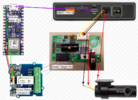
alright got to work on the automated parking mode setup a bit. Spec'ed out some components and put together a wiring diagram
1675471763699.png

I got the Android Phone to Arduino BLE working using a tasker plugin Basic BLE Writer and can set digital pins to high or low using Tasker based automation. Now comes the hard part - building a test circuit
 
Confused. All the links still work to the parts I used.

For the DR900X Plus, I found a switch on Amazon.
https://www.amazon.com/gp/B08DXZ84KG

For DR750-2CH all parts from Aliexpress.

The switch

The adapters

Hey, thanks for this i seen you made this post, I ordered the same but fitting did not fit
 
I believe the earlier plugs only had 2 "connections" ground and supply. Later models have a third to accommodate the newer sensing abilities and wiring harnesses, providing power from the ACC source as well as from the Battery (for parking mode). Thus.. the connectors are slightly different and not interchangeable.
 
I believe the earlier plugs only had 2 "connections" ground and supply. Later models have a third to accommodate the newer sensing abilities and wiring harnesses, providing power from the ACC source as well as from the Battery (for parking mode). Thus.. the connectors are slightly different and not interchangeable.
How can i turn my camera off in garage? with out pulling out the power plug all the time?. My Blackvue does not offer a turn off power button
 
Back
Top