Alternate solution to battery backup power

Ormy

Member
Joined
May 16, 2019
Messages
40
Reaction score
31
Location
UK
Country
United Kingdom
Shortly after I bought my dashcam (see signature) I made this thread about various solutions (thanks to everyone that responded in that thread). TL;DR I settled on upgrading to a 60Ah AGM battery for my car and leaving it at that. With regular driving mid-week it gave full recording over the weekend and I was happy.

Then covid-19 happened and I wasn't driving much at all but still wanted my dashcam to be recording whilst parked. Photovoltaics to the rescue!

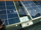
I bought 2x 10W solar panels from ebay costing £25 total. They came already wired with individual diodes to stop the battery discharging through the panels at night. I drilled some holes with a hole-saw in my parcel shelf and glued the panels down with tiger-seal. They are fused at 2A and wired into the car's electrics with spade connectors so I can still remove the parcel shelf easily. I have a distribution block for a small subwoofer amp and 1Farad powercap already in the boot/trunk so it was easy to wire the solar panels in.

I tried to use a cheap digital ammeter to measure the current they were supplying to the battery but for reasons I still don't quite understand I couldn't get it to work without a completely isolated supply (e.g. 9V battery) to power the ammeter itself. Trying to power the ammeter from the cars electrical system led to incorrect current readings. Maybe someone more skilled with electronics can explain exactly what's going on here and any solution?

My solution was was to ditch the digital voltmeter and go with a simple moving-coil analogue ammeter, £5 from ebay. Power-loss within the ammeter itself I've measured in the 'dozens of microwatts' range which is fine.

The photovoltaics charge at about 300-400mA when both in direct sunlight. When overcast they still charge at 20-50mA which is not bad.
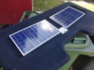
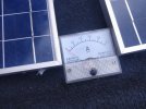
IMG_20200614_161428.jpgIMG_20200614_161432.jpgIMG_20200614_164157.jpgIMG_20200614_165750.jpg
 
Last edited:
You might want to put one of these in the circuit, it has a output voltage limit adjustment so that your battery can't get over charged, and an input voltage adjustment so that your solar panels work at their most efficient voltage and give about 30% extra power, plus an current limit that you don't really need.

https://www.ebay.co.uk/itm/233631160370
 
The current generated should nearly equal the current used by the cam overall, so I doubt that you really need anything else. And even with the cam shut down, that's in the 'trickle charge' range and shouldn't harm a battery that large. I've long thought about something similar so very good to see you have done it (y)

Phil
 
You might want to put one of these in the circuit, it has a output voltage limit adjustment so that your battery can't get over charged, and an input voltage adjustment so that your solar panels work at their most efficient voltage and give about 30% extra power, plus an current limit that you don't really need.

I'm not really concerned about over charging the battery for the reasons @SawMaster pointed out. In the worst case scenario where a series of overcast days causes the battery to drain through the cam without much solar charge until the 11.8v cutoff shuts the cam down, and then a series of very sunny days gives the battery 400mA of charge without any drain from the cam, it would take a week or two of cloudless skies before I might risk damage. We just don't get such weather in the UK. And more often than not I'm parked where the panels are in partial shade half the day anyway.

However a 30% increase to efficiency has me very intrigued indeed. The exact listing you linked to is not from the UK (I only buy from UK sellers if possible), but I found an identical item from a UK seller at a few quid more.

It has this picture in the description;

s-l1600.jpg

The 'output voltage regulation' is self explanatory, I can put a voltmeter across the 'output' terminals and adjust this till I see 14.5-ish volts (right?). But the others? Turn lamp current regulation? Is it referring to my indicator bulbs or something? Constant regulation? MPPT value regulation?

What exactly do these functions do? And more importantly, how do I adjust/calibrate them to optimum settings using a basic multimeter?
 
The 'output voltage regulation' is self explanatory, I can put a voltmeter across the 'output' terminals and adjust this till I see 14.5-ish volts (right?).
13.8 volts is the trickle charge voltage for most batteries, and thus the safe voltage to set for the output. 14.5 would maybe charge a little faster, but normally you are limited by the available power anyway and it will actually sit around 12.7 volts because that is what lead acid batteries charge at when charging is current limited.

To set this, set your multimeter to volts and put the probes across the output with nothing connected, adjust to 13.8 volts.

Turn lamp current regulation?
That sets the charge current when the green indicator LED turns red, doesn't affect the charging, just the charging indicator on the module.
You don't need to set it unless you like playing!

Constant regulation?
That will be the current limit, you can put your multimeter across the output with nothing else connected and with the multimeter set to 10A setting - remember to move the probe connector. Your panels will not supply more than 2 amps so this probably doesn't need adjusting, but you want it set to more than 2A and less than the maximum for the module which is 5A.

MPPT value regulation?
This sets the input voltage, your panels should have a label on them saying something like Vpmax=17 volts, which means that your panel produces maximum power when it is at 17 volts. If you connect it direct the battery at 11.8 volts then it will actually charge at about 12.7 volts and produce proportionally less power.

So put your multimeter across the input, with everything connected, and adjust until you get Vpmax volts.

Actually, since your panel will always be behind darkened glass and often in the shade then it is probably better to go for about 16 volts since Vpmax normally reduces a bit when not at full illumination. You could use your ammeters to set this, adjust for maximum charging current.

Set these in order, output voltage, output current, input voltage.

Note that with 2x 10W panels, you potentially have 20W available, if the cameras are off and you leave the car in full sun in an airport carpark for a week then you could have a boiled dry battery. A small solar panel is fine connected directly to a car battery, but 20W is a bit much and the panels probably have the ability to produce 21 volts once the battery is full, that is enough voltage to kill a battery.
 
First of all thanks very much for your detailed responses.

13.8 volts is the trickle charge voltage for most batteries, and thus the safe voltage to set for the output. 14.5 would maybe charge a little faster, but normally you are limited by the available power anyway and it will actually sit around 12.7 volts because that is what lead acid batteries charge at when charging is current limited.

To set this, set your multimeter to volts and put the probes across the output with nothing connected, adjust to 13.8 volts.

The charging is extremely current limited, connecting and disconnecting the panels makes zero difference to the voltage measured (to nearest 0.1v) across the battery terminals. If I measure the voltage across the panels, as soon they're connected to the battery this voltage drops to equal the battery terminal voltage. Maybe this is a feature of AGM batteries but it seems to pull the charging voltage down to its terminal voltage very easily. E.g. the OEM alternator in my vehicle was a 60 or 70A model, and would charge my old battery at 14.2v even if the battery was flat (down to 9 or 10v). When I installed this AGM battery last year I noticed that after the dashcam had drained the AGM to 11.8v and hit the cutoff, after starting the engine the alternator could only charge at 13-13.2v and so only charge slowly on short journeys, if I had the heated rear screen on (which draws 30-40A) the voltage was drawn down even further and the battery was barely charging at all. I spoke to an auto-electrician, he recommended a bigger alternator so I found 110A one that fit and that got the charging voltage up to 14.3v when the battery was down to 11.8v before charging (14.0-14.1v with the heated rear screen on).

Therefore in terms of the battery health does it even matter where I set this? I'd prefer to just go for whatever is fastest or better for solar panel efficiency.

That sets the charge current when the green indicator LED turns red, doesn't affect the charging, just the charging indicator on the module.
You don't need to set it unless you like playing!

I love playing, that's half the reason I bought the panels in the first place. But this MPPT will be hidden and I still have the moving coil ammeter to show me charging current so I'll ignore it.

That will be the current limit, you can put your multimeter across the output with nothing else connected and with the multimeter set to 10A setting - remember to move the probe connector. Your panels will not supply more than 2 amps so this probably doesn't need adjusting, but you want it set to more than 2A and less than the maximum for the module which is 5A.

When I connect the panel across the multimeter in 10A setting (with nothing else in the circuit) I got less than 500mA from each panel in full sunlight. If it's overcast when this arrives I won't be able to test this properly. Could I connect my car battery to the input with a 5A fuse, my multimeter (10A setting) and a 12v filament bulb in series to the output to set this correctly?

Or can I assume that clockwise = increase and turn it all the way clockwise? The solar panels go through a single 2A fuse so there is no risk of the MPPT seeing 5A.

This sets the input voltage, your panels should have a label on them saying something like Vpmax=17 volts, which means that your panel produces maximum power when it is at 17 volts. If you connect it direct the battery at 11.8 volts then it will actually charge at about 12.7 volts and produce proportionally less power.

So put your multimeter across the input, with everything connected, and adjust until you get Vpmax volts.

Actually, since your panel will always be behind darkened glass and often in the shade then it is probably better to go for about 16 volts since Vpmax normally reduces a bit when not at full illumination. You could use your ammeters to set this, adjust for maximum charging current.

Here is a picture of the label.

IMG_20200614_142830.jpg

It seems like I'm again waiting for a sunny day to set this properly. How can I do it without relying on the weather? Two 9V PP3 in series on the input? What would I connect to the output?

Note that with 2x 10W panels, you potentially have 20W available, if the cameras are off and you leave the car in full sun in an airport carpark for a week then you could have a boiled dry battery. A small solar panel is fine connected directly to a car battery, but 20W is a bit much and the panels probably have the ability to produce 21 volts once the battery is full, that is enough voltage to kill a battery.

By my understanding there will never be anywhere near 20W available. In the image it says the short circuit current is 0.61A. As I said I measured this at around 0.5A with a single panel in full sunlight shorted across my multimeter. When installed to the parcel shelf and behind the glass*, if I disconnect the panels from the battery and short the terminals to the solar panels so they are shorted though the moving coil ammeter it still only reads 400-450mA, that's both panels together. Given the internal resistance of the battery and the resistance of the wires running the full length of the car I can't imagine the panels together will ever deliver more than 8-10W to the battery.

*The glass looks perfectly clear to the eye, but it obviously reflects some light. I know they block plenty of UV-A because photochromic lenses never darken properly when inside a vehicle, do modern solar panels utilise much UVA though?

Final question: at night when the solar panels are not charging their diodes stop the battery discharging through the solar panels. Will this device impair that function at all? Will the battery not drain through the MPPT itself at night? I guess I can verify this for myself when it arrives but just curious. EDIT: I can use an SR560 (I have some lying around) to go between the battery and MPPT in addition to the diodes that came wired in to each solar panel just to be safe. I'm still curious about the answer though.
 
Last edited:
If I measure the voltage across the panels, as soon they're connected to the battery this voltage drops to equal the battery terminal voltage.
When an AGM battery is half empty, it will draw a very large charging current, that is the main reason for using AGM - it charges a lot faster than a standard battery. Your old alternator was fine charging at 13 volts, it has a current limit, although charging at maximum output for long periods was not what it was designed for so may affect lifetime. The bigger alternator will be charging faster.

As for the solar panel charging, yes it will drop to match battery voltage while half empty, however once the battery is full it would quite happily put 21 volts across the battery since the battery will no longer be pulling any charging current. 13.8 volts is a sensible output voltage to set, it will only reach this once the battery is full, which probably won't happen unless you have just made a long journey to the seaside and parked in full sun, in that condition putting 10W into an already full battery is not ideal and will boil some of the electrolyte even if it doesn't kill the battery, 5W is normally considered OK. At other times it will be current limited and match battery voltage, this is only setting the trickle charge voltage.
When I connect the panel across the multimeter in 10A setting (with nothing else in the circuit) I got less than 500mA from each panel in full sunlight.
Yes, you get almost zero power if you do that, but once you connect this voltage regulator, set to 16V input, you will get 20W / 16V = 1.25A input, not sure what the output will be, it would depend on the resistance of the multimeter.
Here is a picture of the label.
17.9 volts for maximum output, but I guess you are best off with around 16 volts, you will see on your ammeters.

It seems like I'm waiting for a sunny day to set this properly. How can I do it without relying on the weather?

You will be able to set input and output voltages, only the current limit is difficult, I guess the default is OK if you can find the documentation. Your 9V batteries won't produce enough power.

*The glass looks perfectly clear to the eye, but it obviously reflects some light. I know they block plenty of UV-A because photochromic lenses never darken properly when inside a vehicle, do modern solar panels utilise much UVA though?
They use some infrared which also gets blocked, don't think they use much UV, but the UV contains most power because of its higher frequency. Yes, you will lose quite a lot.

Final question: at night when the solar panels are not charging their diodes stop the battery discharging through the solar panels. Will this device impair that function at all? Will the battery not drain through the MPPT itself at night? I guess I can verify this for myself when it arrives but just curious.
The diodes in the panels will no longer be needed and could be removed since they will waste a little of the power.
You should however put a diode on the output so that battery power can't flow back into the regulator. You can use one of the diodes from the solar panels.
 
Awesome @Nigel thanks again.

I have a digital voltmeter permanently wired into the battery and mounted on the dash so I'm keeping a close eye on battery voltage at all times, verifying that the alternator is charging etc. If I see that the voltage is a bit high when the engine is off I can disconnect the solar panels easily.
 
Normally people put speakers there, so i am all :)(y)
 
I got the MPPT installed today. Thanks for the clear instructions on setting each adjustment, I followed your instructions exactly and it all worked great. I got confused briefly by the MPPT value/input voltage, turns out it is turned anti-clockwise to increase the value, all the others were clockwise to increase. I set this by putting the ammeter between MPPT and battery and adjusting for maximum current as you suggested. I did this with window glass over the panels, peak current was at an input voltage setting of 16.7v (Vpm stated on the panel is 17.9v). However changing it up or down 2volts didn't really change the current output much.

I did notice that the panels put out 50% power when behind the glass compared to without the glass haha.

It's working in that it is passing current and the LED comes on. However just looking at the reading on the moving coil ammeter (in the pictures, wired between solar panels and MPPT), it didn't seem to increase when adding the MPPT to the circuit vs not having it (I used a DPDT switch to quickly test this). I guess a lot of that 30% extra power comes out as heat from the MPPT itself. Not disappointed though, I still get over-voltage protection for the battery and a day spent outside in sunny weather.

I know you suggested taking the diodes off the individual solar panels but that is not really feasible. The panels are glued to the parcel shelf with tigerseal, no way of getting them off and glued back down and keeping it neat-ish. I have a pack of SR560 lying around so I just put one of those between the MPPT output and the battery which works fine.
 
peak current was at an input voltage setting of 16.7v
It is probably more important that it works best when not in full sun, you might want to try again in less ideal conditions, and then choose a value between your current value and that value.

I did notice that the panels put out 50% power when behind the glass compared to without the glass haha.
So get yourself an open top car and you will get twice the performance ;)

I have a pack of SR560 lying around so I just put one of those between the MPPT output and the battery which works fine.
I hope you set the output voltage with the multimeter connected after the diode, since there should be about a 0.7 volt drop across the diode, and it is the battery voltage that you are trying to set?

it didn't seem to increase when adding the MPPT to the circuit vs not having it (I used a DPDT switch to quickly test this). I guess a lot of that 30% extra power comes out as heat from the MPPT itself
That is a bit disappointing, and yes you do expect to lose some of the gain in heat, but note that the improvement will increase as the battery voltage drops, charging at 11.8 volts would give 11% less charge rate when compared with charging at 13.8 volts if not using the module, using it they will both charge at the higher rate.
 
Shortly after I bought my dashcam (see signature) I made this thread about various solutions (thanks to everyone that responded in that thread). TL;DR I settled on upgrading to a 60Ah AGM battery for my car and leaving it at that. With regular driving mid-week it gave full recording over the weekend and I was happy.

Then covid-19 happened and I wasn't driving much at all but still wanted my dashcam to be recording whilst parked. Photovoltaics to the rescue!

I bought 2x 10W solar panels from ebay costing £25 total. They came already wired with individual diodes to stop the battery discharging through the panels at night. I drilled some holes with a hole-saw in my parcel shelf and glued the panels down with tiger-seal. They are fused at 2A and wired into the car's electrics with spade connectors so I can still remove the parcel shelf easily. I have a distribution block for a small subwoofer amp and 1Farad powercap already in the boot/trunk so it was easy to wire the solar panels in.

I tried to use a cheap digital ammeter to measure the current they were supplying to the battery but for reasons I still don't quite understand I couldn't get it to work without a completely isolated supply (e.g. 9V battery) to power the ammeter itself. Trying to power the ammeter from the cars electrical system led to incorrect current readings. Maybe someone more skilled with electronics can explain exactly what's going on here and any solution?

My solution was was to ditch the digital voltmeter and go with a simple moving-coil analogue ammeter, £5 from ebay. Power-loss within the ammeter itself I've measured in the 'dozens of microwatts' range which is fine Compaq Presario M2260AU [184/239] System memory map continued.

The photovoltaics charge at about 300-400mA when both in direct sunlight. When overcast they still charge at 20-50mA which is not bad.
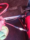
View attachment 52665View attachment 52666View attachment 52667View attachment 52668
I'm hoping to find a more simplified/convenient way to handle battery backups in our network closet. We're currently using 4 CyberPower UPS units, but my IT manager is interested in finding something like a single unit that could serve the purpose in a better way. Right now, each UPS is essentially backing up a single PDU, though as with everything, it's not quite as simple as that.

This area is home to 6 or so switches, a handful of physical servers and a pair of ESXI hosts for virtual machines. Roughly 12,000 watts of equipment, if that's a helpful measurement.
Researching this has me stumped, I'm not sure what to look for. What are you guys using for your solutions? I'm more looking for some broad strokes recommendations rather than specific models - even pointing me in the direction of an appropriate vendor would be very helpful.
 
Back
Top