Capacitor Standby Power Mod

Cobber

New Member
Joined
Dec 31, 2016
Messages
19
Reaction score
3
Location
Perth
Country
Australia
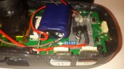
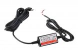
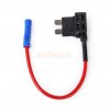
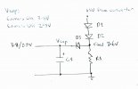
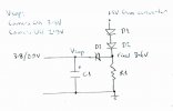
After being frustrated with my new G1W-CB forgetting its settings every couple of days, I came up with a mod to keep the capacitor fully charged at all times. Only 3 diodes and a resistor need to be put inside the camera and two wires go from the camera to a 12V to 5V converter that is connected to an "always on" 12V supply in your fuse panel with an "Add-a-Fuse" connector.

If you are handy with a soldering iron (or know someone who is) and willing to do a bit of fiddling inside your camera, then this simple mod will ensure your settings are never lost again, even if the capacitor is on its last legs.

I have created a PDF file on how to do it here. The circuit diagram is simple as you can see:
1.jpg

As explained in detail in the PDF file, it is based on the 0.7V drop across forward biased diodes.

The 360 ohm resistor draws a constant 10mA current to provide 3.6V to the anode of D3. The voltage across the camera's capacitor is 3.8V when it is on, reverse biasing D3 and disabling the mod. When the camera is off, the capacitor's voltage falls to 2.9V, forward biasing D3 and allowing it to charge from the converter via D2 and D1.

The 12V to 5V converter I used is freely available on eBay and shuts down automatically if your car battery drops below 11.6V, not that 10mA will do that for a long time.

The fuse holder is also commonly available on eBay and at auto accessory shops.

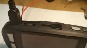
I have attached some pictures of how it was done.
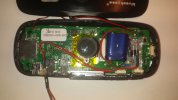
2.jpg 3.jpg 4.jpg 5.jpg 6.jpg

If you have any queries, please ask.
 
An elegantly simple and interesting solution but I wonder if simply replacing the super-caps would have done well enough instead? The eventual loss of date/time with all cap-powered cams is something of an issue for those not using it frequently though normally it takes a week or more for the loss to occur with most cams. My G1Wc held time around 10 days as does my Mobius which leads me to think perhaps your caps aren't up to snuff. And as you probably know many of the caps produced in China these days (essentially almost all of them) have a reputation for poor quality and of barely meeting minimum specs when new then deteriorating quickly from there :( I've seen numerous Chinese motor-start capacitor failures in HVAC equipment and have had to replace them with a more expensive US-made brand (which wasn't easy to find) as that failure and replacement schedule was becoming almost an annual servicing event with every unit :eek: I haven't researched it but I'm sure there has to be a similar source for a better-than-usual supercaps for dashcams. That would reduce the problem but there's just no overcoming the lack of capacity while still keeping the size small enough to fit inside a dashcam case so I guess it's an issue that will continue. It's good that the cams will still record anyway; losing that would make discharged supercaps disastrous!

Phil
 
Whether cams are powered by battery or capacitors, their ability to store settings will degrade over time. This is a new camera and I had expected more. The caps may very well be cheap and nasty, but I wanted a solution that was long-term. Because of the heat here in Perth, battery cams are out of the question. So I figured, why not have the best of both worlds and let the car battery be the storage source? The same idea could be used with any cap cam, as I would imagine the voltages would be much the same.

I must add that the cam wasn't actually in the car while testing, but running from a powerbank for short periods in my office. It's quite feasible the caps weren't getting fully charged. This cam is going to be my rear window one.

My A119, which is my front camera, has the button cell backup battery which works a treat. This is my first time with dash cameras and loss of settings seemed to be a common issue online with the G1W's, so I looked for a way to overcome it. Just thought I'd share it for anyone who was interested.
 
Last edited:
I don't believe that resistor is necessary. In this circuit it is the voltage that creates the current (through the resistor) not the other way round.
Regardless of what's happening with R1, if Vcap is less than 2.9v (5-3*0.7) current will flow through the 3 diodes charging the capacitor.
Might you be willing to test this theory?

You could however move the resistor so it's right next to the GND point in your diagram, or in series with the diodes. (Either way taking out the bridge from top to bottom.) Then it would limit the current charging the capacitor. I have no idea if this is desirable, I haven't looked into best practice for charging supercapacitors.

Edit> It looks like the voltage drop across these diodes rises with current flow, so they will act as current limiters even without a resistor, e.g. at 1A the forward voltage rises to about 0.95V:
https://www.fairchildsemi.com/datasheets/1N/1N4004.pdf
 
Last edited:
@Rajagra

I didn't want to make my explanation of how the mod works too technical that people would not understand.

My reasoning for using R1 is that when the camera is on, Vcap is 3.8V, meaning the diodes will always be forward biased. That means both the camera and the converter would be trying to charge the capacitor at the same time, possibly confusing the camera's charging circuit.

By adding R1, a reference voltage of 3.6V is created, which enables D3 to automatically do the magic of switching the current to the converter on and off.

When the power from the converter is first applied (with the camera off) C1 will start charging immediately. The current would be high at first, decreasing as it reaches the full standby voltage of 2.9V. That is why I use 1A diodes and the increased drop across the diodes is not important during this time. Once the capacitor is fully charged to 2.9V, then we can assume 0.7V as the diode drop. The internal resistance of D1-D3 and the circuitry of the converter should protect C1 from excessive charging current.

Your observations are correct, and I initially didn't use R1 in the design theory, until I realized the need for a reference voltage. A zener diode type setup seemed an overkill and unnecessary.

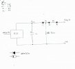
It may help to see the circuit redrawn like this:

7.jpg
 
Last edited:
I like this better than a zener regulated circuit because a component failure here will not cause an unsafe condition (blowing the supercaps). If a zener failed the excess voltage could possibly do that ;) I prefer to avoid explosions inside my vehicle and I've seen what blown caps can do to thin plastic housings like dashcams have :eek: I've been so long out of the game that I'd have to check references to find component values but I can still understand how the circuit works :)

A user-replaceable RTC battery is the best solution but with cheap cams you're only going to get the barest minimums of everything- you don't get what you don't pay for. Being that I'm not much on appearances I've considered using larger externally mounted supercaps but haven't played with that concept since all my cap-powered cams function well enough for me as-is.

Phil
 
I don't think the resistor is needed for the reason you give. It might however stop the capacitor from overcharging over the very long term (towards 5V).
Figure 2 in the datasheet for the 1N4004 that I linked is very interesting. At 0.6V forward voltage you get a small 0.01A current. At 0.8V you get 0.2A.

If you left out the resistor, you'd get these situations:
When Vcap=2.0V you get 1V across each diode, allowing about 2A current flow.
When Vcap=2.3V you get 0.9V across each diode, allowing about 0.5A current flow.*
When Vcap=2.6V you get 0.8V across each diode, allowing about 0.2A current flow.
When Vcap=2.9V you get 0.7V across each diode, allowing about 0.05A current flow.*
When Vcap=3.2V you get 0.6V across each diode, allowing about 0.01A current flow.
When Vcap=3.8V you get 0.4V across each diode, allowing very little current flow. But still some?
(*) I haven't worked out exact values from the logarithmic graph.

Under normal circumstances when either the camera PCB or your circuit is keeping the cap charged, it will never drop under 3.8V, so current through your circuit will be low.

I'll see if I can work out what the cap voltage is limited to if the resistor is left in.

Edit> Aha. at a steady state,
V2=Vcap
V2=360*I(D2)
I(D2)=Forward current of 1N4004 @((5V-V2)/2)
For Vcap=V2=3.8V, I(D2)=Forward current of 1N4004 @0.6V=0.01A
And this roughly matches V2=360*0.01=3.6V

I think I get it now!
 
Last edited:
@Rajagra

You are not an electronics engineer by any chance? I am a technician by trade.

Your need to delve into the theory of how the mod works reminds me of when I was in the Air Force. I would design a circuit, build it and test it, then use it. The engineering officer would then spend weeks trying to prove why it would never work.

I measured all the voltages in the circuit with the camera on and off, and they agreed with what I had predicted. To me, that was enough to know I had gotten it right. Too much knowledge can often be a hindrance rather than a benefit, which is why I kept my initial explanation simple.

I'm glad you "get it" now, and no offense is intended.
 
I have a saying I use in my business: "If it looks good, works good, and stays that way there can't be too much wrong with it." :cool: That's all that really counts, and all that anyone can really expect from anything.

Phil
 
Yep. If it works don't fix it. It doesn't pay to over-think things.
 
With respect, I never suggested at all that your circuit wouldn't work. I merely suggested a simpler circuit might work too, and I DID ask about testing. The K.I.S.S. principle applies here.

It is entirely possible that the resistor is not needed. The current through these diodes when the forward voltage is under 0.6V is tiny.

Given the comments above this one of mine, is it not hypocritical to dismiss MY suggestion out of hand?

Taking out the resistor might actually work better. The present version would struggle to charge the capacitor to 3.2V (5-3*0.6)

Did you test whether your circuit actually charges a capacitor that already has a low voltage - in a reasonable time? That would be the real test, not measuring voltage points in a system where the capacitor is already charged.

I'm not being confrontational. Your idea is a good one and I'm just suggesting possible simplifications / improvements.

Sent from my tap-to-talk using Tapatalk
 
I am beginning to regret starting this thread. I don't think you understand the purpose of the mod.

The mod is only meant to charge the capacitor to 2.9V (not 3.8V) - the voltage it falls to when the camera is switched off. Only the camera itself charges it to 3.8V (and only when the camera is on). Vcap is not V2, but V2-0.7V. Yes I did check how long C1 takes to reach the 2.9V. It was almost instantaneous.

R1 is absolutely necessary, because it is what enables D3 to turn off current from the converter when the camera is on.

You don't have to understand it to use it. The offer is there for anyone who wants to give it a try. If not, then simply ignore it.

I am heading out for the night, so won't see any replies. I think I have said all I need to say at the moment. I leave you in peace.
 
Last edited:
I do understand it perfectly. But like I said, I'm not being confrontational, so I'll just drop it.

Don't regret making the thread. Your idea is a great one, thanks for sharing it.

Sent from my tap-to-talk using Tapatalk
 
@Rajagra is 100% correct, there is no need for the resistor and the circuit will perform exactly the same and the car battery will not see any additional load when the engine is off.

According to the OP, "By adding R1, a reference voltage of 3.6V is created". The resistor doesn't "create" the voltage at that junction, that voltage will be there with or without the resistor! All what the OP is doing is when the camera is off he is charging the capacitor with 5v through 3 diodes in series. So when the camera is off the voltage across the capacitor would be 5V minus 3 junction diodes, theoretically 5V-(3 x 0.7V)=2.9V. In reality the voltage across the capacitor will be slightly higher, approximately 3.2V. That is because once the capacitor is charged, practically there wouldn't be much current going through the diodes so their forward voltage wouldn't be more that 0.6V as you can see from the diode curves voltage vs. current. Now when the camera is on, the capacitor is charges by the camera's charging circuit, according to the OP to 3.8V and in that case all 3 diodes will not be forward biased so no current will be flowing through the diodes.
 
Last edited:
Now when the camera is on, the capacitor is charges by the camera's charging circuit, according to the OP to 3.8V and in that case all 3 diodes will be reverse biased so no current will be flowing through the diodes.

Wrong. The diodes would still be forward biased. R1 is used to prevent this happening.
 
I cannot believe how such a simple circuit can be so misunderstood. So let's see if I can explain it better.
7a.jpg
Take the right-hand vertical leg. R1 is used to draw 10mA of current from the converter at all times. This clamps the voltage at the cathode of D2 to 3.6V

The voltage may not be exactly 3.6, but there is no need for a regulated voltage to be made using a zener diode type setup.

When the camera is OFF, Vcap will be approximately 2.9V, again not critical, but less than 3.6V

This means D3 will be forward biased, enabling C1 to remain charged to approximately 2.9V because of the voltage drop caused by D3, D2 and D1.

When the camera is ON, the camera's charging circuit will raise Vcap to approximately 3.8V

This means D3 will now be reverse biased, preventing any current flow to D2 and D1. This also means the converter and camera are not both trying to charge C1 at the same time.

If there was no R1, then D3 would not be able to provide this function, because all 3 diodes would be forward biased all the time, whether Vcap is 3.8V or 2.9V, since the voltage from the converter is always 5V.

It is a simple circuit of 4 components, but quite clever in its operation, something circuits should always aim for. I cannot explain it any better, and if someone doesn't understand how it works, then you will just have to trust me when I say it does.
 
@Cobber, with all due respect, except for the resistor constantly drawing ~10mA the circuit will perform exactly the same. Again, there is nothing wrong with your original circuit, you simply don't need the resistor and the extra load on the car battery!

As I said, with the camera Off, the voltage at the junction of your D2 and D3 will almost be the same with the resistor or without it. There maybe only a few millivolts difference due to the fact that without the resistor (very little current through the diodes) the forward voltage of D1 and D2 would be slightly lower so the voltage at the D2 and D3 junction will be slightly higher (by exactly the same amount). When the camera is On the voltage across the capacitor is 3.8V as you said so the differential voltage across all 3 diode is only 1.2V, ~0.4v across each diode which is not enough for them to conduct.

You dont have to believe me, what do I know, I am only a EE with over 30 years of experience designing electronic hardware and I am not here to argue with anyone.
 
Last edited:
@upsss, The difference between being an engineer and a technician is technicians think more simply.

The idea that the diodes would not conduct without R1 (because of the low differential voltage) is not something a technician would think of, nor has it been explained that way previously. We simply think in terms of biasing.

While I take your word for it, to me, having R1 ensures the biasing always works. I chose 10mA as a nominal trickle current. You could use 5mA (720 ohms) or even 1mA (3,600 ohms), although the 3.6V would then go higher due to the reduced current.

To me, it is better to be safe than sorry, but I understand what you are saying.
 
After being frustrated with my new G1W-CB forgetting its settings every couple of days, I came up with a mod to keep the capacitor fully charged at all times.
I think we should just focus on this part.
Maybe anyone doing this mod would like to test whether the resistor is useful themselves, it's up to them.

With the resistor the capacitor will not overcharge. Without it, there's a theoretical chance it would (tending towards 5V.) Might take weeks months or years, I don't know. The data sheet chart just says the current would be miniscule.


Sent from my tap-to-talk using Tapatalk
 
The capacitor will never charge to more that 5V minus the 3 junction diodes. With the camera Off the capacitor sees a constant load (although very small) from the RTC and the processor which will be in sleep mode including its own leakage. Wasn't that the original problem that the OP tried to solve where the capacitor over time lost charge and the camera lost its settings?
 
Back
Top