I had mine set up this way for a while.
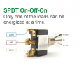
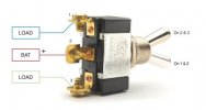
I used a SPDT switch. That type of switch has a center lead and 2 positions. In one position the center is connected to the left lead, and in the other position it's connected to the right lead. You just have to put your ACC power into left, and BATT power into right, and you can choose which source gets sent to the camera. There's no center position, so the switchover is fast enough that the camera keeps working as long as the 5V converter or camera can handle the very short power dip
Don't use a switch type that will connect both ACC and BATT at once, because you'd be effectively combining 2 circuits and who knows what bad things could happen
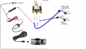
Just to be clear, on the picture below it's 1-Battery 2-output to camera 3-ACC
Then the - line from the camera goes to ground
")