DIY Install: Viofo A229 Duo

AS87

Member
Joined
Apr 19, 2016
Messages
43
Reaction score
19
Country
India
Dash Cam
Viofo A229 Duo
The initial plan was to get the Viofo A129 Pro Duo 4K but thanks to this forum, I knew that there is a successor coming in the form of the A229 series so I decided to wait for a bit for all the initial niggles are worked up and then I can get one. Finally decided to bite the bullet and get the Viofo A229 Duo with the hardwiring kit and CPL filter set. Prior to this dashcam, I used the Mini 0806, Viofo A119S and DDPai Mini.

The Setup: Viofo A229 Duo + Viofo HK4 hardwiring kit + Viofo CPL Filter + SanDisk Extreme Pro (128GB)
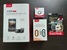
1. Viofo A229 Duo + CPL + HK4 + SanDisk Extreme Pro 128GB card.jpg

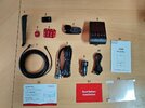
A229 Duo - Package Contents
4. Viofo A229 Duo contents.jpg
The Package contents are:
  1. Trim panel removal tool
  2. Viofo's SD card reader
  3. Rear Camera unit
  4. Main Front camera unit
  5. Spare 3M sticker pad for the rear camera
  6. Spare 3M sticker pad for the front camera
  7. Coaxial cable - To connect the front camera and rear camera. 6m long thinner in dia for easy and a cleaner install
  8. USB-C cable to connect to the car's 12V socket - IF hardwiring is not being done.
  9. Viofo's 12V USB power adaptor
  10. USB-A to USB-C cable to connect the front camera to the computer to transfer files and/or upgrade the firmware
  11. A229 Duo User manual
  12. Warranty policy card with installation details
  13. Initialization instructions are to be followed BEFORE the installation is done to verify whether both cameras are working as intended or not
  14. Windshield static stickers (x 2) were provided for a cleaner installation. This is to avoid any sticker residue on the windshield and if one wants to change the position of the camera post the installation.

Viofo HK4 Contents (L to R - The box; 2 pairs of Low-profile MINI ATM fuse taps with 5A fuses included; Hardwiring kit & HK4 User manual)
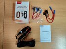
5. Viofo HK4 Hardwiring Kit Contents.jpg

Viofo CPL Filter (For the front camera)
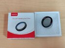
3. Viofo CPL Filter.jpg

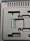
Front Camera - GPS mount (USB-C Port which not only powers the camera but also records the GPS coordinates + speed data)
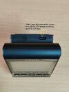
16. GPS Power port.jpg

5-pin connection
17. Five pin for the GPS port.jpg

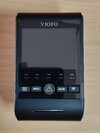
Front Camera - Drivers side view
Front Cam - Front side.jpg

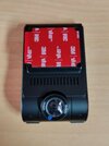
Front camera - Windshield side view
Front Cam - Rear side.jpg

Front camera - Side view of the ports and connections
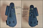
18. Front Camera Sides.jpg

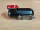
Rear camera
Rear Camera.jpg
 
Installation Images - WIP

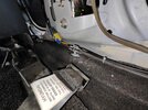
Cowl panels were removed to pass the rear camera coaxial cable. Used the path followed by the rear windshield washer pipe

5. Scuff plate trim removed to pass rear cable.jpg

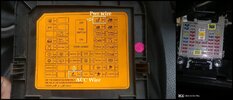
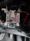
Fuse Box and the selected fuse for Hardwiring
8. Fuse box.jpg

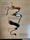
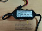
Viofo HK4 Hardwiring kit explained - All the connections
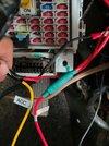
9. Viofo HK4 Hardwiring kit explained.jpg

Battery voltage protection controller
10. Battery saver switch.jpg

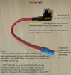
Fuse tap cable connections explained
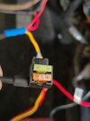
10. Fuse tap cable.jpg

Factory ground point - Connected the black wire from the HK4 kit
11. Ground point.jpg

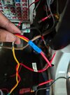
Crimping done for the ACC wire (yellow)
12. ACC Wire crimped to fuse tap.jpg

Secondary fuse added for dashcam (5A)
13. Fuses added into the fuse tap.jpg

Heat shrink tubing was placed over the crimp and applied heat for the tubing to shrink
14. Heat shrinking done.jpg

Both the fuse tap cables are connected at the designated points
15. Hardwiring completed for both ACC & Power wire.jpg
 
Installation Images

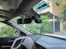
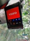
The front camera was installed, and both cables were connected. Extra wires were pushed into the headliner

19. Front camera mounted and cables connected.jpg

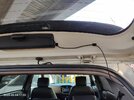
The rear camera was connected and the extra wiring was held by clips. The camera is mounted on the HMSL cover
20. Rear camera mounted and connected.jpg
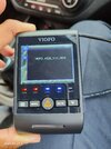
Boot-up screen with the standard 'Viofo' chime
21. Welcome screen.jpg

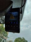
Indication on the screen (along with voice notification) when the clip is locked after pressing the emergency button.
23. Indication when file is locked (button pressed).jpg

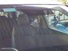
Front Camera - View from outside
25. Front camera visibility from outside.jpg

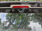
Rear Camera - View from outside
24a. Rear camera visibility from outside (zoom in).jpg
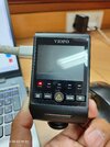
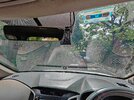
Glare on a sunny day
26. Glare on the windscreen.jpg

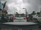
Front Camera - a screenshot from the recording
27. Screen grab from the front camera.JPG

Rear Camera - a screenshot from the recording
28. Screen grab from the rear camera.JPG

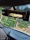
Size of the rear camera when seen from the IRVM
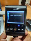
Size of Rear camera from IRVM.jpg
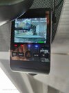
 
  • Coming to the installation part, either one can use the 12V power socket provided or go for the hardwiring route. Since I also wanted to access the parking mode function, I have hardwired the dashcam using the Viofo HK4 kit.
Items Required for the Installation:
  • Zip ties
  • 12V tester pen
  • Trim panel removal tool
  • 1/4' socket set
  • Crimping tool
  • Wire stripper
  • Hot air gun
  • Heat shrink tubing
  • Multimeter
  • Fuse puller - located in the fuse box in the engine compartment
Note: Disconnect the negative terminal of the battery before starting the installation.

Fuse Selection for Hardwiring
  • The hardwiring kit comes with 2 pairs of fuse tap cable (Low-profile Mini) type fuses so this installation requires the use of one pair of fuse taps i.e., one for ACC (yellow) and the other for Poer (red) wire. Using the 12V tester pen, choose the appropriate fuse that stays ON when the ignition is OFF (for Red wire) and the fuse that turns ON only when the ignition is ON (for Yellow wire).
NOTE: While choosing the fuse, never select critical items like ABS and airbags which may impact the safety and functioning of the car in the event of any failure. In my case, I chose the 'Cigar Lighter fuse' for the ACC (yellow) wire fuse tap and the 'Power seat fuse' for the Power wire (Red) fuse tap. Neither of them is critical in terms of the safety and functioning of the car.
  • Once the fuse points are selected, strip the wires to the appropriate length and crimp them into the provided fuse tap cables individually. Before crimping is done, slide a piece of heat shrink tubing over and crimp the wire into the butt connector. Ensure the crimp is tight and wouldn't slide out over time. Slide the heat shrink over the connector and shrink it using the heat gun.
  • From the fuse box remove the 'original circuit' fuse and fit it into the holder that is near the 'pins of the fuse tap cable' and then add the appropriate 'secondary fuse' into the fuse tap cable and slot the fuse tap cable into the chosen location in the fuse box. Repeat the same for the second fuse tap cable too.
  • Locate the factory ground point to connect the third wire in the hardwiring kit. Once located, loosen the bolt and connect the black wire (GND) to the terminal and tighten the bolt fully. Ensure the connection is tight. Do NOT over-tighten.
  • Before winding up and fixing all the panels etc back, connect the negative terminal on the battery and connect the USB cable to the GPS port of the camera and test if the camera turns ON and whether both the cameras are working as required.
  • If the parking mode function is being enabled, set the appropriate voltage on the voltage configurator using the selector switch comprising of 4 positions i.e., (a) 11.8V, (b) 12.0V, (c) 12.2V and (d) 12.4V. I have set the switch at 12.2V.
  • Once everything is good and working as it should, refit the trim panels back and tidy up the interiors.
Camera Mounting Locations

1. Front Camera

I chose the location to be near the IRVM which is placed in the centre of the windshield so the recording would be even to look plus coverage would be better. Accessing it from the driver's seat would be easier too with minimal obstruction. I didn't use the static stickers provided in the package since I stuck the camera directly to the front windshield (on the 'black dotted' border). Once the camera is turned ON, stop the recording, turn ON the WiFi and connect to the app on the smartphone. Switch to 'live view' mode to align the CPL filter with as much as possible minimal glare. After the CPL filter is adjusted, adjust the angle of the camera lens to have a '50% - sky and 50% - road' view for optimal functioning of exposure functioning.

2. Rear Camera
At the moment it is mounted on the HMSL cover that is just above the rear windshield. While viewing the files, I felt that the demister lines are making the video look odd hence would be removing the rear camera from the current position and mounting it directly onto the rear windshield glass between the demister lines for better video quality from the rear camera.
NOTE: While choosing the mounting locations, keep in mind to have an area where the windshield wipers move to have good quality footage available in the rainy season too. Else the footage would be of no use once the glass area is dirty and/or wet.
  • Once the cameras are mounted and connected, insert the memory card into the slot and format the SD card 'inside' the dashcam for optimal functioning. Generally, the first boot-up with the memory card installed prompts the user to format it first and once completed, the dashcam starts recording automatically. A voice message is also provided once the format is done (whether successful or not).
 
  • The camera can be operated either using the 2.4" screen or the Viofo App found on Play Store. For the sake of convenience, I use the application most of the time for viewing the live feed and to carry out any changes in the settings (if required).
Viofo smartphone Application - Home Screen (Android)
1. Viofo App opening screen.jpg

Without connecting to the WIFI of the dashcam, the following screens appear when trying to connect to the App. Click on 'to system settings' will open the WIFI settings in the smartphone
WIFI Connection steps.jpg

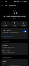
Select the "5G_Viofo A229" network (SSID) and enter the default password to connect it for the first time. Change the password of the WIFI as desired and reconnect:
Camera WIFI ID.jpg

Following is how the videos are 'labelled and saved' on the memory card. The videos ending with the letter 'F' are from the front camera. Videos ending with the letter 'R' are from the rear camera. Also, note the file size for each of the files. The settings I've kept are - Loop recording set at 3mins with Max resolution and Max Bitrate while recording. The average file size for output from the front camera is 440MB and the Rear camera file size is 350MB
9. Videos labelled on the SD card.jpg

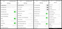
"Settings section" in the Viofo smartphone application.
App Settings.jpg
Video Resolution: 1944P 24fps + 1944P 24fps, 1440P 30fps + 1440P 30fps, 1080P 30fps + 1080P 30fps
Loop Recording: 1, 2, 3, 5 and 10 minutes. I have set it at 3 minutes.
Video Bitrate: Low, Medium and Maximum. I have set it at Maximum
WDR: On or Off.
WiFi Channel: 2.4GHz or 5GHz. Set it at 5GHz if the smartphone supports it and also for a faster video download rate.
Time Zone: Set as desired. For India, it is +05:30
Time Synchronisation: Once the 'Time Zone' is updated, synchronize the time between the smartphone and the camera for even time and date info during recording.
G-Sensor: Low, Medium and High. I have kept it at 'Low'.
Parking Mode: Three options are available - (a) Auto-Event Detection (AED), (b) Time Lapse and (c) Low Bitrate Mode. I have set it at AED for now.
Parking Recording Timer: Duration that the camera will record 'after' parking mode is enabled and once the timer has lapsed, the camera will shut down. If kept OFF then the dashcam will continue to record till the low-voltage cutoff happens. If the timer is set then the dashcam will record for that duration and then turn afterwards.
Enter Parking mode timer: Off or 90sec. In this, if the setting is kept at 'OFF' the camera will immediately switch to parking mode after the ACC is turned OFF. If '90 sec' is selected, the camera will switch to parking mode 'after' 90 seconds is done post ignition switch off.
GPS Info Stamp: (a) Speed Only, (b) GPS coordinates Only, (c) Speed + GPS coordinates.

NOTE: Every time the firmware is updated on the camera, these settings are reset automatically and would require to be re-done.

Firmware version during first boot up (Verison No.: V1.0_0926):
Firmware version during first turn on.jpg

Firmware upgrade in progress (the 'PWR' LED will flicker and will restart automatically
Firmware update in progress.jpg

Latest Firmware (Verison No.: V1.2_20230413): Thanks to @rcg530, I downloaded this firmware and upgrade it on the dashcam
Latest Firmware.jpg
Post the firmware update, the screen display contents have changed a bit. GPS Speed is shown at the bottom right corner in Green (If GPS is connected) and Red (If GPS is not connected). The resolution chosen is displayed in the top right corner.

Latest Firmware Screen changes.jpg
 
So far the dashcam has been running without any major issues and so is the SanDisk Extreme PRO memory card working normally. In all these days of usage, have observed one minor issue, GPS latching delay by the dashcam.

It takes almost 5-10 minutes after the recording starts for the dashcam to recognise the GPS signal. Till that time the GPS LED keeps on flashing. Not sure what the issue could be.

Any pointers?
 
Uploaded a few videos from the dashcam to my YouTube channel. Links inserted for all the videos:


Sir, you are not alone. Even I have night time footage issue. It is beyond pathetic. @viofo says it is due to my headlights, which I got changed at the first place because the problem existed with previous ones too.

Can you imagine this being the night time quality of 300 Euro+ dashcam? Terribly disappointing.

@Batish Here are a few videos from my A229 Duo. I have also tried to lower the exposure for the front dashcam from 0.0 to -1.0. There is some difference and sort of better in the way it is capturing the registration plates.
 
So far the dashcam has been running without any major issues and so is the SanDisk Extreme PRO memory card working normally. In all these days of usage, have observed one minor issue, GPS latching delay by the dashcam.

It takes almost 5-10 minutes after the recording starts for the dashcam to recognise the GPS signal. Till that time the GPS LED keeps on flashing. Not sure what the issue could be.

Any pointers?

Weather condition can have an effect on GPS signal usually during storms.
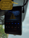
Another possibility is the type of windscreen mesh on the glass this could have some metal in it so similar that reduces the signal strength to the GPS.

1688254687467.png

Your image with my comment.

Cheers.
 
So far the dashcam has been running without any major issues and so is the SanDisk Extreme PRO memory card working normally. In all these days of usage, have observed one minor issue, GPS latching delay by the dashcam.

It takes almost 5-10 minutes after the recording starts for the dashcam to recognise the GPS signal. Till that time the GPS LED keeps on flashing. Not sure what the issue could be.

Any pointers?
I've personally gotten a bad VIOFO GPS mount, but mine would not connect to GPS at all. I know from anecdotal experience that others have also had issues with their GPS modules, it's rare, but you might try switching out your GPS module.
 
Weather condition can have an effect on GPS signal usually during storms.
Another possibility is the type of windscreen mesh on the glass this could have some metal in it so similar that reduces the signal strength to the GPS.

View attachment 66049

Your image with my comment.

Cheers.
AFAIK, it is just a black dotted sticker kind of pasted on the windshield border. No presence of metal in it.

I've personally gotten a bad VIOFO GPS mount, but mine would not connect to GPS at all. I know from anecdotal experience that others have also had issues with their GPS modules, it's rare, but you might try switching out your GPS module.
The issue arises during the first connection after a long gap like say 8+ hours. After the first connection is established, rest all times it latches immediately.
 
MTK3337 GPS chipset does not have any internal memory so it can not sore almanach and ephemeris data. It cause long (cold) start of GPS module. I'm really do not understand reasons why still use it in dashcams
Also you may view GPS signal strength info in my FW mod (look into A229 FW thread)
 
Last edited:
AFAIK, it is just a black dotted sticker kind of pasted on the windshield border. No presence of metal in it.
It's not a black plastic sticker. When your bored try removing it with a plastic catalyst product and let me know the result.

I'm guessing your dash hasn't been damaged by UV either most likely due to a metal coating on the windscreen.

Neither may affect your truck in this case but it is possible.

My suggestions aren't flippant they are considered.

Fin.
 
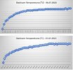
Installed a MODDED firmware for the dashcam thanks to @Dex_. Here's how the dashcam temperatures are during usage while driving from home to work and back.
Dashcam Temps.jpg
 
Back
Top