Hello fellow users, new member here with a question about hardwiring. I am planning to hardwire my A119S in to a 2011 Chev Impala.
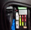
Nearly every fuse I’ve tested is hot with the ignition switched off. Only one 10 amp RAP fuse appears to be switched, the only problem being that it’s very recessed in the fuse block and surround by other devices (as shown in the photo). This fuse block is located on the passenger side interior near the floor.
This is preventing me from using an Add-A-Circuit, right now there is no way one can fit in there. So, I am wondering if anyone makes a longer version of this that would fit in there, or maybe someone has an idea for a work around? I’m thinking of possibly getting some male and female spades and making up some extensions of an inch or two that would go between the block and the Add-A-Circuit.
Thanks, I hope someone will have some suggestions that are better than mine!


")
