HK3 hard wire kit - terrible voltage regulation

v81

Member
Joined
Mar 15, 2021
Messages
67
Reaction score
52
Location
Melbourne
Country
Australia
So, not an owner of a Viofo cam myself, have been going through nightmares trying to install one with my father.

First - this is not a 129 issue, this is a HK3 hard wire kit issue.
Posting here as the related camera is an A129 Pro Duo

First install resulted in a camera that functioned for 20-40 seconds and then froze.
Powering it from a USB power bank, or any other Automotive 12v - 5v USB adapter worked fine, so we blamed the hard wire kit.
We receive a 2nd hard wire kit, dad installs it and similar issues.

An it's no wonder....
Have a look at the output of these things...
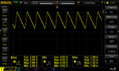

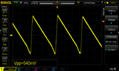
DS1Z_QuickPrint13.png
On average 2.59Vpp and voltage swings from 4.52 to 7.12
On what is supposed to be a regulated 5 output!

Test setup...
Rigol DP832 power supply - Ch1 13.8v simulating battery - Ch2 13.8v simulating acc - Ch1 & Ch2 grounds tied.
Rigol DS1054Z Oscilloscope measuring USB V output at the PCB
Ruideng HD35 DC load configured for 1Amp (also tested at 500mA, 100mA and 50mA with similar results) to simulate dash cam.


So we have 2 HK3 kits that do this so far.
They both power a Navman dash cam OK in this state, this was before we'd tested, had we known the output was this ugly we wouldn't have plugged the supply into anything we valued.
This could be common, or a bad few units.
Given it works intermittently and works with dashcams with lower power requirements there is a fair chance this might be happening to units that otherwise appear to be working, possibly killing them over time or rendering them unreliable.
For anyone not deeply knowledgeable we normally measure power supply ripple in millivolts (0.001v) not full volts.
That's how bad these are.

So 2 for 2 so far.
Will take this up with Viofo and the seller.
Possible bad batch, but I'm concerned this might be wider spread.
There is no easy way to do it but if you have the facilities to test your own HK3 kit output I'd suggest you do so, but i suspect few would have the right gear.
I'm open to doing testing for people, but im in Melbourne, Australia so could be logistically difficult.

Edit re low voltage cutout
Forgot to mention, tested the low voltage disconnect on the bench, notes are poor as it was not the primary reason i was at the bench.
Testing 11.8V low voltage showed the device to disconnect at 11.0v
Testing again at 12.4V the device disconnected at approx 11.4v
Did not test 12.0 nor 12.2v disconnect.
end edit

I'll post a follow up as i learn more.
 
Last edited:
Edit re low voltage cutout
Forgot to mention, tested the low voltage disconnect on the bench, notes are poor as it was not the primary reason i was at the bench.
Testing 11.8V low voltage showed the device to disconnect at 11.0v
Testing again at 12.4V the device disconnected at approx 11.4v
Did not test 12.0 nor 12.2v disconnect.
how long did you wait at each voltage level before lowering the input voltage further?
 
In early February 2021, I ran some tests of a 2-wire and three different 3-wire HK3 power adapters to see at what voltage level they cutoff the power to the dash camera. I purchased a brand new HK3 power adapter for the test and used it with a functional VIOFO A129 Pro 4K camera that I temporarily removed from one of my cars for the tests.

The first two HK3 adapters would not make the A129 Pro camera go into parking mode. Those two HK3 adapters would not cutoff the power to the camera until they were 1 volt or so below the selected cutoff value on the HK3.

The third HK3 that I purchased, after I returned the first two as defective, would properly make the camera go into parking mode. That HK3 would cutoff power to the camera at about 0.25 volt below the selected value. I know there will be some variance in the actual cutoff vs the selected cutoff voltage, but a 1 volt variance (that was present with the first two HK3 units) is too far off.

I created a video on my channel showing that testing. At the 11:11 point in the video is where I show the HK3 testing (the third unit that "worked").

** Video link removed - being reworked to correct a testing error **
 
Last edited:
@v81 I tested briefly Viofo's HWK few months ago with basically the same result (and probably for the same reason :D ). The problem here is that this is output without (or very low) load... And if you check the circuit you'll find out why (it's like this by design).

With A129Pro hooked up it's a bit more settle with 640mVpp around 5.3V, if i recall correctly. Actually i did some research and wrote a text about this but then i realized it probably wouldn't be worth the effort and Viofo won't do a thing so i only posted a basic info in one of the threads here and replaced the HWK with another power supply (since i have B-124 i didn't need the voltage control thing)


Btw: Check also frequency of the sawtooth wave, you'll be amazed as well... :D
 
Last edited:
I created a video on my channel showing that testing. At the 11:11 point in the video is where I show the HK3 testing (the third unit that "worked").
not doubting your first two power supplies that you said were faulty but your test of this third kit for voltage cutoff is not correct, perhaps you're not aware of how these work, once the hardwire kit reaches the cutoff voltage selected (+/- 0.1v) it will hold power for 90 to 100 seconds before turning the power off to the camera, you were backing off the voltage further before this time had elapsed, watching the time from when you switched to 12v it was right around that amount of time when it cutoff
 
how long did you wait at each voltage level before lowering the input voltage further?

As i said above it was a quick test, and not the main interest.
On further testing it does appear to have a delay period if 1 minute and 30 seconds after reaching the cutoff point.
Time seems fairly repeatable.
With 12.4v set i got no cutout at 12.3v (20 minutes) and after 1m30s got a cutout at 12.2v
Didn't test for the precise voltage point at where it began to work.
Seems repeatable, and i'd be happy enough with that.
Sad the cutoff point is not too precise, but no terrible.

That regulation though... that is a show stopper.

In early February 2021, I ran some tests of a 2-wire and three different 3-wire HK3 power adapters to see at what voltage level they cutoff the power to the dash camera. I purchased a brand new HK3 power adapter for the test and used it with a functional VIOFO A129 Pro 4K camera that I temporarily removed from one of my cars for the tests.

The first two HK3 adapters would not make the A129 Pro camera go into parking mode. Those two HK3 adapters would not cutoff the power to the camera until they were 1 volt or so below the selected cutoff value on the HK3.

The third HK3 that I purchased, after I returned the first two as defective, would properly make the camera go into parking mode. That HK3 would cutoff power to the camera at about 0.25 volt below the selected value. I know there will be some variance in the actual cutoff vs the selected cutoff voltage, but a 1 volt variance (that was present with the first two HK3 units) is too far off.

I created a video on my channel showing that testing. At the 11:11 point in the video is where I show the HK3 testing (the third unit that "worked").

Do you still have this gear, and by any chance access to an oscilloscope and DC load?
Would be great to see how 'working' they are, even the unit that does seem to successfully power a camera.

Given the issues here I'd not plug a HK3 into anything that i valued.
Just that it works sometimes or with some things is not enough, it 'works' with dad's Navman but still has 2.5v of ripple and an output that averages 6v and swings over 7 volts when it is supposed to be 5v.

As for the low voltage cutout it's not uncommon for devices like these to have hysteresis or a delay of sorts, i think that was what jokiin above was suggesting might be the case.
My initial tests for 10-20 seconds didn't trigger a cutoff, but running the test longer it does indeed work, though the voltage is still not super accurate it wasn't as bad as it initially appeared.

Maybe re-run your tests with 0.1, 0.2 and 0.3v under the cutoff point and let each test sit for up to 10 mins and see if you get different results.

As for the parking mode, the parking mode trigger as far as i can tell is the dashcam losing 5v on pin 4 of the usb port.
This is usually the ID pin on a mini or micro USB port.
Pin 4 is fed by the yellow wire from the PCB and should drop to 0v when the yellow 'acc' input wire loses power.
Pin 1 is VCC (5v) though i have observed that as the load on the power supply increases the regulation falls apart (as per the scope screen above) and the average voltage increases.
Pin 5 is GND

For reference the model A129 Pro Duo draws almost 1 Amp exactly on the 5v side of the supply, or high 900mA's with no rear camera or GPS module (ie, on the bench).
Configured settings do matter, these were highest bitrate, 4K mode.
Efficiency of the regulator is pretty poor also as far as modern switch mode regs go, i measured 69% where I'd be expecting 80% as a minimum
Not a big deal to a running vehicle, but in park mode this will equal 10's of minutes of lost run time.
A well designed fixed voltage switched mode reg should be hitting 90% really.
 
As i said above it was a quick test, and not the main interest.
On further testing it does appear to have a delay period if 1 minute and 30 seconds after reaching the cutoff point.
Time seems fairly repeatable.
will be repeatable as the cutoff time is an intentional value that is programmed into it
 
I know our dashcam PS's are rather simple, cheap, and nasty devices but that's more like an earthquake than ripple, and it would also explain the not infrequent instances of EMI from HWK's disturbing car systems, as well as some PS's having a choke on the output.

I don't expect great things here, but this is more than a little bit shocking to me. 2.59V avg vpp is NOT regulation, it's madness. That's over 50% of the 5VDC we are expecting :(

Phil
 
@v81 I tested briefly Viofo's HWK few months ago with basically the same result (and probably for the same reason :D ). The problem here is that this is output without (or very low) load... And if you check the circuit you'll find out why (it's like this by design).

With A129Pro hooked up it's a bit more settle with 640mVpp around 5.3V, if i recall correctly. Actually i did some research and wrote a text about this but then i realized it probably wouldn't be worth the effort and Viofo won't do a thing so i only posted a basic info in one of the threads here and replaced the HWK with another power supply (since i have B-124 i didn't need the voltage control thing)


Btw: Check also frequency of the sawtooth wave, you'll be amazed as well... :D
Just need to correct you there, this is not with no load as you suggest.
Check the details of the test setup in my OP, i apply a 1 amp load for the testing.
It actually gets worse with load, not better.

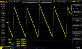
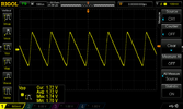
Following tests were with 50mA, 100mA and 500mA loads.... (just beware OP was the most detailed test and is set to Dc coupling, these are all AC).
These tests are quick and dirty, and the formatting of the captures are not the same, but since you mentioned load i thought I'd post them.
HK3 50mA load.png
HK3 100mA load.png
HK3 500mA load.png


will be repeatable as the cutoff time is an intentional value that is programmed into it
This sudo / time based hysterisis makes sense, just seems like a long time.
 
Last edited:
Given the issues here I'd not plug a HK3 into anything that i valued.
Yes, that was my conclusion too, but it is sold specifically for hardwiring Viofo dashcams with a long power cable, it is not sold as a phone charger, doesn't even work as a phone charger since it doesn't have micro USB!

Just that it works sometimes or with some things is not enough, it 'works' with dad's Navman but still has 2.5v of ripple and an output that averages 6v and swings over 7 volts when it is supposed to be 5v.
When you say that it is supposed to be 5V, that is based on it being USB compatible, but if it was never intended to be a general purpose USB power supply or match the USB specifications, then the only requirement is that it is compatible with Viofo dashcams, and if they want to increase the voltage a bit and build their dashcams to use higher voltages and cope with a lot of ripple, then I'm not sure there is anything wrong with that, they could even make it AC if they wanted!

So, are you sure that the problems you have had are due to what you have seen on the oscilloscope, or could there be another explanation? For most people, the HK3 works fine, and I guess most of them look the same on the oscilloscope...
 
Just need to correct you there, this is not with no load as you suggest.

Check the details of the test setup in my OP, i apply a 1 amp load for the testing.
It actually gets worse with load, not better.

Following tests were with 50mA, 100mA and 500mA loads.... (just beware OP was the most detailed test and is set to Dc coupling, these are all AC).
These tests are quick and dirty, and the formatting of the captures are not the same, but since you mentioned load i thought I'd post them.

.....

This sudo / time based hysterisis makes sense, just seems like a long time.
Shoot, Ruideng HD35. Despite i have the exact same tool i kinda didn't get used to the name and completely missed it in your post :D . My apologies.

Ok, in that case, there is something fishy going on. It bugged me a bit after you pointed out the load so i tested my second HWK for A129Pro (i have also A139 so may be later). Same load tool, LiFePO4 battery source (13.2V) and from about 0.5A it was stable 5.13V, 530mVpp up to 1.5A (haven't tested anything above).


Yes, that was my conclusion too, but it is sold specifically for hardwiring Viofo dashcams with a long power cable, it is not sold as a phone charger, doesn't even work as a phone charger since it doesn't have micro USB!
Good point, but saw wave with random Vpp and frequency isn't the best as an "electromagnetically silent" power source.
 
Last edited:
...but saw wave with random Vpp and frequency isn't the best as an "electromagnetically silent" power source.
Depends a bit on what is connected at the other end. There will be another switching voltage regulator in the camera, not a nice resistive load, it would be interesting the see the oscilloscope with the real load attached...
 
Doesn't matter, it still will produce "signal" all over the place. I know that particular cable is shielded but... (EDIT: Ooops, sorry, i was thinking about USB cable for rear camera for some reason :D There is no shielding whatsoever from HWK.)

Do you mean to measure it after the load or literally just "with"? It's basically as i've said before, due to "non-linear" load, changes randomize the wave (which is even worse for EM production).
 
Last edited:
Doesn't matter, it still will produce "signal" all over the place. I know that particular cable is shielded but... (EDIT: Ooops, sorry, i was thinking about USB cable for rear camera for some reason :D There is no shielding whatsoever from HWK.)

Do you mean to measure it after the load or literally "with"? It's basically as i've said before, due to "non-linear" load the changes randomize the wave (which is even worse for EM production).
Well I don't expect that you will get that nice sawtooth wave with it plugged into a camera, not sure what to expect, could be that the camera smooths off all the teeth!

It doesn't appear to be a particularly high frequency for causing interference issues...
 
not doubting your first two power supplies that you said were faulty but your test of this third kit for voltage cutoff is not correct, perhaps you're not aware of how these work, once the hardwire kit reaches the cutoff voltage selected (+/- 0.1v) it will hold power for 90 to 100 seconds before turning the power off to the camera, you were backing off the voltage further before this time had elapsed, watching the time from when you switched to 12v it was right around that amount of time when it cutoff
I reran the voltage cutoff test this morning using the HK3 set to cutoff power at 12.2 volts. You are correct in that the HK3 did seem to cutoff the power to the camera around 100 to 110 seconds with the voltage level set to 0.1 volt below the selected value. I'll rework my video with the correct testing procedure and results. Thanks for the info.
 
When you say that it is supposed to be 5V, that is based on it being USB compatible, but if it was never intended to be a general purpose USB power supply or match the USB specifications, then the only requirement is that it is compatible with Viofo dashcams, and if they want to increase the voltage a bit and build their dashcams to use higher voltages and cope with a lot of ripple, then I'm not sure there is anything wrong with that, they could even make it AC if they wanted!
It is very dangerous to design products with standard connectors that use non-standard voltages. Doing so will cause damaged equipment and potentially fires.
USB is a standard. The A129 pro has a standard USB port on it for power that can be used to access the memory card from a computer. It expects and works with 5V.

The A129 pro is very sensitive to input voltage. If the voltage drops too much below 5V the camera will malfunction or crash. The A129 pro draws quite a bit of current through the cable, so if the resistance of the cable is significant, it will cause a voltage drop sufficient to cause the A129 pro to fail.
In my car I was powering the A129 pro with a 15' commercially available USB cable and was having trouble with the camera crashing. I replaced this cable with a cable I made myself using lamp cord (much lower resistance) and have not had trouble since.

The ripple shown in the oscilloscope captures is certainly enough to crash an A129 pro.
 
Yes, that was my conclusion too, but it is sold specifically for hardwiring Viofo dashcams with a long power cable, it is not sold as a phone charger, doesn't even work as a phone charger since it doesn't have micro USB!
No one has even mentioned phone charging in this thread. I'm not sure where you got that from.
By expensive device i was referring to a multi hundred dollar dash camera..... the very thing the kit is sold for.
When you say that it is supposed to be 5V, that is based on it being USB compatible, but if it was never intended to be a general purpose USB power supply or match the USB specifications, then the only requirement is that it is compatible with Viofo dashcams, and if they want to increase the voltage a bit and build their dashcams to use higher voltages and cope with a lot of ripple, then I'm not sure there is anything wrong with that, they could even make it AC if they wanted!
I have no issue with them tossing any voltage at it that they wish, but when they decide to us a USB connector and not another connector a reasonable person would conclude that they should comply with USB spec, at the very least voltage wise.
If it were a barrel plug or some other plug then they can do whatever they want, but they provide in the box a cigarette lighter to USB power supply.
And ignoring that for a moment, it can be drawn as a reasonable conclusion that they are trying to use USB voltage to power it.
The HK3 supplies a near perfect 5v with no load, and the camera runs perfectly from an in spec USB power supply. These things should lead a reasonable person to conclude that they were intending to work within USB spec.

Regardless of any of that, they could use any voltage they want, but that regulation is the worst i have ever personally seen.
Yes, there will be additional regulation in the camera, but that does not excuse this behaviour.
Yes the load the camera applies is not purely resistive, but that fact actually favours my test, if hooked up to the camera the results would be at the very least the same, possibly worse.
Using a linear lab power supply and purely resistive load gave the device the most favourable conditions to operate in, and it was still terrible.

So, are you sure that the problems you have had are due to what you have seen on the oscilloscope, or could there be another explanation? For most people, the HK3 works fine, and I guess most of them look the same on the oscilloscope...
Given the camera works perfectly from any power source other than the HK3, yeah... I'm pretty sure.
And whilst i am suggesting that all HK3's do this, i don't think they are all this bad, otherwise no ones unit would work.
I think they all do this, it's a poor design, but i do reasonably doubt they are all as bad as the 2 examples i have here.
I hope you can see I'm trying to be reasonable and objective here.

If you don't have experience with switch mode regulator output they can vary in ripple, but as i said in the first post, we usually measure that in milli volts.
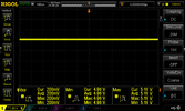
Here is a switching reg module i got on eBay, 10 of these for about AUD$5 including post, with the same 1A resistive load, tested yesterday when i was demonstrating to my father at the bench here what they should look more like...
Ebay reg.png
An order of magnitude less ripple and it's just a 50 cent no name eBay regulator.
Coincidently it happens to be significantly more efficient too.
Surely they can use a reg as good as or better than this 50c unit in a $30 power supply.

Shoot, Ruideng HD35. Despite i have the exact same tool i kinda didn't get used to the name and completely missed it in your post :D . My apologies.

Ok, in that case, there is something fishy going on. It bugged me a bit after you pointed out the load so i tested my second HWK for A129Pro (i have also A139 so may be later). Same load tool, LiFePO4 battery source (13.2V) and from about 0.5A it was stable 5.13V, 530mVpp up to 1.5A (haven't tested anything above).
Yeah, it's disgusting. It appears yours is not as bad as this one, and thus that is probably why it works.
530mVpp is pretty rotten, but not in the 2590mVpp ballpark i got.
At least with your figures it's not too unsafe to plug in.
I think I have a bad batch of something that is a bad design to begin with.

Depends a bit on what is connected at the other end. There will be another switching voltage regulator in the camera, not a nice resistive load, it would be interesting the see the oscilloscope with the real load attached...
As i mentioned above, the resistive load is actually more favourable, if i used the camera it would be the same or worse.
And no, I'm not going to test this to prove a point, I'll not be plugging a regulator that bad into a device we hope to use.
Given how much dirty power has gone into the unit we're actually quite within our rights to request a new camera.
If the scope capture is not ringing alarm bells for you then you might be misunderstanding just how terrible these readings are.

I reran the voltage cutoff test this morning using the HK3 set to cutoff power at 12.2 volts. You are correct in that the HK3 did seem to cutoff the power to the camera around 100 to 110 seconds with the voltage level set to 0.1 volt below the selected value. I'll rework my video with the correct testing procedure and results. Thanks for the info.
100-110 seconds is a long time and thus can easily catch us out (caught me in my first rough test).
The fact you plan to re-work your video with new findings makes you an awesome and honest human.
Keep doing your thing.

It is very dangerous to design products with standard connectors that use non-standard voltages. Doing so will cause damaged equipment and potentially fires.
USB is a standard. The A129 pro has a standard USB port on it for power that can be used to access the memory card from a computer. It expects and works with 5V.

The A129 pro is very sensitive to input voltage. If the voltage drops too much below 5V the camera will malfunction or crash. The A129 pro draws quite a bit of current through the cable, so if the resistance of the cable is significant, it will cause a voltage drop sufficient to cause the A129 pro to fail.
In my car I was powering the A129 pro with a 15' commercially available USB cable and was having trouble with the camera crashing. I replaced this cable with a cable I made myself using lamp cord (much lower resistance) and have not had trouble since.

The ripple shown in the oscilloscope captures is certainly enough to crash an A129 pro.
You make excellent points.
On the voltage drop over the cable, I tested at the output of the reg PCB, so the voltage at the end of the cable would be much worse, and I think this is where our problem might lie.
As per the OP scope capture the Avg min voltage is 4.52, compound that with a resistive voltage drop over that length of cable with the camera drawing a full 1 amp...

If my ohms law is right this time of the morning i calculate the loss to be an additional 240mV, and given how rough the incoming regulation is you'd need a giant filter / reservoir cap in the dash cam to compensate, which it simply don't have, not for an incoming voltage with such a gross swing.
So cable resistance = ~ 0.24 ohms (Rohde&Schwarz HMC8012 multimeter leads nulled out)
Current - 1A (Dash cam running with GPS and rear camera attached)
Voltage = 4.52 (average reading at low point)
We're looking at an additional loss of 240mV, so 4.52v - 0.24v = 4.28v
A good portion of the internals would be running on other post regulators (3v3, 2v5, 1v8 etc..) , but for any internals looking for close to 5v that is terrible.

I think it's more than fair to say that these are terribly designed units.
They are obviously not all as bad as the ones i have, but they are bad.
 
I'm actually in the process of making my own power supply, or at least a prototype on the bench.
So far I'm using a micro controller with 10bit ADC, i probably should be using an analogue comparator, but my experience in analogue electonics is a bit poor.
Main concern was quiescent current (power draw when the circuit is 'off', ie not supplying dash cam).
The HK3 has a quiescent current draw of 3mA with is actually quite a lot when it's supposed to be in low voltage disconnect mode.
I think I can design a superior unit in terms of reliability, functionality and efficiency both on and in LVD mode.
I think I'll set my goal to 1mA or less in the LVD state and efficiency to 85% or better whilst running.
VS the HK3 3mA and 69% this should result in less power used per minute of run time of the camera in park mode, thus overall extending run time by 10's of minutes, possibly even an hour or more.
 
The HK3 has a quiescent current draw of 3mA with is actually quite a lot when it's supposed to be in low voltage disconnect mode.
I thought that was camera powered down current, effectively the power used by the GPS module, low voltage cutoff was a lot less when I measured it...
 
I reran my low voltage power cutoff tests with the VIOFO HK3 today. I tested all of the voltage selections (12.4/12.2/12.0/11.8) and all of them behaved the same.

I've reworked the video and in it I show a test run of the HK3 with it set to 12.4 volts for the cutoff voltage level.

I start off the test by powering up the dash camera by simulating a "car start" event. I then turned off the accessory power supply (ignition off) and the VIOFO A129 Pro camera would go into parking mode. After the A129 was in parking mode, I would reduce the voltage level provided by the power supply in multiple steps. I would test each voltage level for 120 seconds and then reduce the voltage again and wait again. When the voltage level was reduced to 0.1 volt below the HK3 configured value, the HK3 would cutoff power to the dash camera after a 95 to 100 second waiting period.

I've uploaded the updated video my YouTube channel.

 
Back
Top