How to install Panarama X2

timbilt

New Member
Joined
Feb 6, 2015
Messages
19
Reaction score
23
Country
United States
Hello,

My Panarama X2 just arrived (thank you Jon!). I know it says to get it installed by a mechanic, but I don't wanna pay them to do something that I can figure out by myself. The thing I can't figure out is, what is the yellow cable marked 'B+'? I watched some YouTube videos showing how to hardwire your dash cam, but they only have a ground and red cable. This has a black (ground), red (marked 'acc'), and yellow (marked 'B+'). Is there a video demonstrating this?
 
So what is the real difference? When would you use the B+ and when would you use the acc? Like, if you attached the 'acc' (red) to a fuse that was always on, wouldn't that be a permanent source?
 
So what is the real difference? When would you use the B+ and when would you use the acc? Like, if you attached the red to a fuse that was always on, wouldn't that be a permanent source?

this is why they suggest professional installation ;)

it needs a permanent and a switched power source to work correctly, you need both connected, it's not a matter of when you should use them
 
Hi Happy to help

1) EDIT don't use an old school light probe tester.
http://www.bcae1.com/testlite.htm

Use a multi meter voltage tester. This will quickly help you confirm which fuses are hot or not with the car on/off for step #3

2) You'll then want 2 of the add-a-fuse
http://www.amazon.com/s/ref=nb_sb_noss_1?url=search-alias=automotive&field-keywords=add a fuse&sprefix=add+a,automotive
Using a 10a fuse on the new added wire side of the new double fuse is good enough. Use the same rating on the original side.

3) Connect the two power wires to the appropriate fuse

Yellow B+ should go to a power source that is energized 24/7 such as the power seats
Red ACC should go to a power source that is only energized when the car is running such as the cigarette lighter power.
(some cars this is active even when the engine is off, if so use another one)
Ground can be bolted or clamped to any bare metal surface of the car around the fuse box you'll see something.

I'll try to create a video in the near future.
 
Last edited:
if it's a late model vehicle you should use a multi meter not a test light, you can damage the electronics in the car by using a test light
 
Good advice, I thought they were pretty harmless guess not.
late model vehicles definitely should not use test lights, this is another reason why you want to pay a pro to do the job, damage a computer and it starts getting expensive, makes professional install look very cheap

a good car radio installer is the best option for this kind of work, aside from the electrical they're used to dealing with the trims and concealing wires

More sound advice, time is money as well. I would use yelp to find a local car audio install place they will install everything the correct way. If you're in the San Francisco bay area, City Car Radio is a good shop. http://www.yelp.com/biz/city-car-radio-san-francisco
 
My user manual provides full fuse layout. Fuses are 5, 10, 15, and 20 amp. If I tap a 5 amp fuse like the interior lighting, I can use a 10 amp for the cam 5 amp original?
 
For switched red ACC or non-switched yellow BAT?

If ACC, Some interior lighting circuits stay hot for awhile even after the car is off so not ideal for parking mode operation.
 
It's all installed and working beautifully - upgraded to firmware 1.02.03.

I went out and bought:
1. Multimeter - thanks to jokiin for this recommendation.
2. Two Add-A-Circuit accessories for tapping into two fuses.
3. A couple fuses of different amperage (I used two 10 amp fuses for the cam). I connected to the AWD Park Assist (red, acc) and the Alarm Siren Control Module (yellow, B+).
4. One Fuse Remover, which makes it very easy to remove fuses from the fuse box. It actually came with a little assortment of fuses.

I couldn't have done this without almost super-hero-like help and support from Jon from Pier28, and also jokiin. Sure, I could have easily gone and paid a professional (which I do recommend), but I enjoy doing things myself very much. It took me a while because I had to do research on how to do everything. In the end, I hardly think a professional would have done much of a better job, if at all.

Recommendation for Do-It-Yourselfers:
1. Be patient, and allocate ample time based on your level of experience. If you're like me and don't know what you're doing but researching and learning as you go along, take it slow.
2. Make your you purchase/borrow the items mentioned above.
3. Make your that you have basic tools like screw drivers and pliers. These will help in removing your interior lining, crimping wires, and removing the bolt when you attach your ground wire.
4. Vehicle's User Manual. This comes in handy when you want to figure out where something is, how to remove something, or what a specific fuse is attached to. If you don't have it then search the Internet for diagrams for your vehicle make and model.
5. To test if a fuse is good, turn the nob on the multimeter to the Ohm icon, then put the red lead from the multimeter on one end of the fuse, and the black lead on the other end of the fuse. It doesn't matter if the fuse is in the fuse box or not.
6. To test a fuse for power/voltage, turn the nob on the multimeter to the DC icon, connect the black lead to a ground near the fuse box, connect the red lead to either end of the fuse. Obviously the fuse must be in the fuse box. The red wire should tap a fuse that goes off immediately when the car goes off (not one that stays on for a while then goes off, like interior lights as Jon pointed out). The yellow wire should tap a fuse that is always on. Be careful when you connect a Add-A-Circuit module in order to tap a fuse --- a lot of these modules say something like "2 to 10 Amps", in which case you should not tap a fuse that is greater.
7. Be gentle when you remove interior lining and trims, the plastic clips that hold them in can break if you do it wrong.

Parking mode and everything works! I tested it and took a test drive. I got the polarizing lens, I recommend it --- check it out https://www.youtube.com/watch?v=SN4uB3s5tAU.

Cheers,
Tim
 
great info,

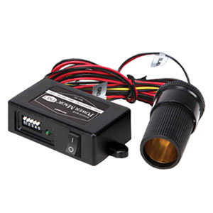
I take it this is the same way as installing the power magic.
 
Question:

If you are using a third party voltage cut off device like the power magic pro do you combine both wires (acc and b+) from X2 or do you only use the B+ wire?

The power magic pro requires a male 12 volt cigarette adapter to plug into it.
gzzqCL8.jpg
 
Question:

If you are using a third party voltage cut off device like the power magic pro do you combine both wires (acc and b+) from X2 or do you only use the B+ wire?

The power magic pro requires a male 12 volt cigarette adapter to plug into it.
gzzqCL8.jpg

Here's how I did it with the MotoPark PANOBDP, you should be able to use this as a guide.

X2 Power Control set to OFF

MotoPark PANOBDP has 5 wires
https://dashcamtalk.com/forum/threa...charge-prevention-device-ms-multi-safer.4603/

Fusebox side:
1) Red ACC (connected to Switched ACC power)
2) Yellow BAT (connected to Non-Switched BAT power)
3) Ground (connected to bare metal frame of car ground)

Camera side: (only 2 of the 3 X2 wires here)
4) White (connected to X2 Yellow BAT)
5) Black (connected to X2 Black Ground)

Connect X2 3rd wire (Red ACC) to Switched ACC power shared with 1) above

How it works:
A) power up, confirm MotoPark is blinking normal
B) engine off will remove power to ACC
C) X2 goes into Parking Mode.
D) If voltage drops below set level, X2 gracefully shuts down

From my customer:

Jon,

The new MotoPark voltage cutoff device and new front camera are working well. Thanks again for sending me those.

Sorry it took a few days to get back to you about the lights. I put the MotoPark device in a hidden spot and kept forgetting to check the lights.

Anyway, here is how the lights are -
With the parking mode settings on the camera for voltage and timer cutoff set to OFF:

When the MotoPark (parking mode) is on
Key in the ON position: red light blinks quickly twice, then there is a slight pause
Key in the OFF position: red light blinks at even pace

When the MotoPark (parking mode) is off
Key in the ON position: solid red light
Key in the OFF position: no red light
 
Last edited by a moderator:
Connect X2 3rd wire (Red ACC) to Switched ACC power shared with 1) above

Thanks for the quick reply but some thing seems wrong about that line. Aren't you are circumventing the voltage cut-off devices control by wiring it that way?

Is the X2 red acc wire just a simple (off/on) trigger to tell the X2 to enter exit parking mode or does it also provide 12 volt power to the X2 when the car is on?

That is, the yellow B+ wire is parking mode power only and the red acc wire is the parking mode (off/on) trigger AND powers the X2 when the car is on.

Here is the original post I based the reply above on. It was how I tested on the bench and not in the actual vehicle. I think I might have translated something wrong bench to real world. Let met think what I missed and I'll edit the original reply above. Here's what I posted in the Private Panorama section:

Bench test confirmed, X2 works with Power Control set to OFF and MotoPark PANOBDP added as a work around

MotoPark PANOBDP has 5 wires
https://dashcamtalk.com/forum/threa...charge-prevention-device-ms-multi-safer.4603/

Simulated Fusebox side:
1) Red ACC (connected to bench + power #1)
2) Yellow BAT (connected to bench + power #2
3) Ground (connected to bench - ground)

Camera side: (only 2 of the 3 X2 wires here)
4) White (connected to X2 Yellow BAT)
5) Black (connected to X2 Black Ground)

Connect X2 3rd wire (Red ACC) to bench + power #1 shared with 1) above

A) power up, confirm MotoPark is blinking normal
B) Remove both red wires from bench power #1
C) Confirm X2 goes into Parking Mode.
D) Turn knob on JetStream to lower voltage until MotoPark cuts off
E) Watch X2 gracefully shut down every time.

Success!
cleardot.gif

dPsVwlTm.png
 
Last edited by a moderator:
Connect X2 3rd wire (Red ACC) to Switched ACC power shared with 1) above

Actually I think you are correct! :D

The X2 will still need a trigger to tell it to go into parking mode. That's why you wired the ACC separately.

If I combine the ACC and B+ X2 wires with the power magic pro power the X2 will think it is in "drive mode" all the time.

(I will test) Thanks again!
 
Thread starter Similar threads Forum Replies Date
H X2 1
Similar threads
Enercell Install Trouble
Back
Top