Bad idea. The cells are serio-parallel, so they should have the closest specs possible to each other (doesn't matter there is balancing circuit or feedback for overdischarge... ).
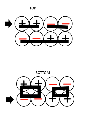
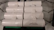
Btw: @know610 How good are you with soldering station? It requeres station/tip with pretty high heat capacity (if you don't have a welder) and the cells in B-124 seem like welded directly in pairs and there isn't much space on the sides...
Just a basic soldering guy. So I guess I shouldn’t mess with it to be safe. Thank you
") ? If it require solder, i have no issue with it.
? If it require solder, i have no issue with it.