Installing a Cellink Neo?

RavenManiac

Active Member
Joined
Jun 18, 2015
Messages
899
Reaction score
184
Location
Williamsburg, Virginia
Country
United States
Dash Cam
Viofo A129 Duo, mini 0806 (RIP)
I read that the Cellink Neo requires a 10-amp circuit. If that's the case, what amperage circuit should I try to tap into?

Also, how does this get wired into an A129 Duo with an HK3 Hardwire Kit?

Thanks!
 
Last edited:
Assuming that you are referring to a non-ignition switched constant +12V source, sometimes the best thing is a good old ring terminal, inline fuse holder, a fuse (of course!), and High Temp GXL All-Copper stranded wire (NOT Copper Clad Aluminum wire - CCA) connected directly to the positive battery post.

Though keep in mind that works best with top post batteries, and I have not seen the engine compartment of a 2019 Mazda 3, nor its battery. I would probably choose a minimum of a 14 gauge wire, though if you never intend to add any other powered accessories to that same wire, then the wire should be the same or lower gauge (fatter) than whatever comes with the Cellink Neo.

If you need a switched +12V source, the same plus a ignition triggered relay could be used, though perhaps someone else might have a better idea for your Mazda. (It would probably be wise to use an ignition switched +12v that turns off as soon as the key is removed, or when the push-to-start/stop/off button is pressed, so the Cellink Neo not pull any power from the car battery after the alternator has stopped running.)
 
Last edited:
We recommend hardwiring the Neo to a fuse between 15A-30A.

The A129's hardwire kit can be spliced with the Neo's 3-wire output cable. Everything's labeled for ACC, Batt and ground.
 
We recommend hardwiring the Neo to a fuse between 15A-30A.

The A129's hardwire kit can be spliced with the Neo's 3-wire output cable. Everything's labeled for ACC, Batt and ground.

So, the only switched circuits in the 2019 Mazda 3 that are large enough to supply power to the Neo and are able to accommodate a fuse tap are:
F8: 15-AMP, Engine Control System
F10: 15-AMP, Engine Control System
F12: 15-AMP, Engine Control System

Are any of these okay to use?
 
If you take 10 amps out of a 15 amp circuit, there has to be a high risk of taking more than is available.
If the supply to the fuse tap is from a 100 amp bus and you install the fuse tap so that the fuses are in parallel then no problem, if you connect them in series then expect to blow the original fuse at an inconvenient time.

If you are not sure that the supply to the fuse tap is capable of more than the 15 + 10 amps then you should only use that power to switch a 15+ amp relay to switch power from a high amp fuse, or maybe direct from the battery.

Hope that makes some sense?
 
Yes, that makes perfect sense. So, basically, I would need to install a relay that would be triggered by the 15-AMP switched circuit and send power directly from the battery to the Cellink Neo, correct? So basically, it would look something like this except the switch would be the 12V ACC circuit and the lights would be the Neo. I actually only need a 4 prong fuse, but I can't find that as a complete kit on Amazon.
 

Attachments

  • 71ZlG3AbxhL._SL1500_.jpg
    71ZlG3AbxhL._SL1500_.jpg
    110.7 KB · Views: 25
Last edited:
Yes, that makes perfect sense. So, basically, I would need to install a relay that would be triggered by the 15-AMP switched circuit and send power directly from the battery to the Cellink Neo, correct? So basically, it would look something like this except the switch would be the 12V ACC circuit and the lights would be the Neo. I actually only need a 4 prong fuse, but I can't find that as a complete kit on Amazon.

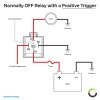
First off, if you intend to use a relay, you should buy one with a matching socket. The relay will plug into the socket, and the socket will have a short lengths of wires attached in order to make your wire connections. If you intend to install this relay within the engine compartment, then you should be sure to buy a waterproof relay and socket. That diagram you included only complicates things. Most standard relay pins are referred to by numbers, usually 85 and 86 for the activating circuit, and the activated circuit 30, 87 and 87a -- 30 to 87a is normally closed (connected) and 30 to 87 is normally open (unconnected). Then you pass an activating current though pins 85 and 86, the relay connects pins 30 to 87 and disconnects pins 30 to 87a. In this manner, one circuit with low current requirements can switch another circuit though which a much greater current can flow. (This describes a SPDT relay -- Single Pole, Double Throw)

For the Cellink Neo connections, you won't need to connect 87a to anything. Tape it off safely and securely.
The rest of the pins would be connected like this:
85 to ground (opposite to din standard to accommodate a relay with built-in diode if used)
86 to 12V ignition source (opposite to din standard to accommodate a relay with built-in diode if used)
30 for 12V constant (at battery post perhaps)
87 to Cellink Neo 12V ignition switched input.

In a mechanical relay, a flowing current between pins 85 and 86 energize a wire coil which switches the higher current circuit via electromagnetism -- it literally changes the position of an internal switch topped an iron tip. (That's the click you'll hear.) These days there are decent relays and unfortunately many not so decent cheaply made relays, which are not well designed to last as long as others used to. You can probably discern between the good and the bad by reading the associated reviews. (If you would like to verify your choice for any red flags, feel free to ask via pm.)

One last very important note, and perhaps even the most important of all depending upon which ignition switched fuse you choose to trigger the relay. In modern cars, computerized electronics turn on and off many if not most or all of the circuits, and they can be very sensitive to certain types of electrical issues, and especially so in the case of a reverse high voltage current caused by the collapsing electromagnetic field of a de-energized relay coil. So you must protect the car's activating 12v ignition switched circuit by installing a diode or a resistor into the relay circuit -- or better yet, choose a relay with one already installed within its case. It would also be best if you could find a circuit that is already isolated from the car's electronics by a factory installed relay. The factory relay will protect the car's electronics, and you can safely use the switched side of that relay to trigger your new additional relay. (Though I would still suggest a relay with a built-in resistor or diode anyway. They're easily found and they're usually of better quality too.)
 
Last edited:
Yes, that makes perfect sense. So, basically, I would need to install a relay that would be triggered by the 15-AMP switched circuit and send power directly from the battery to the Cellink Neo, correct?
Yes, then you will only use around 50 milliamps from the ECU circuit to power the relay, no risk of overloading that circuit, and the Neo can easily take as much as it wants from the new circuit.

As in your diagram, if you take power off the battery, do include a fuse to protect your new wiring from short circuits, and best to use an automotive relay since they are designed to cope with the heat, water, oil, fuel etc. in the engine bay.

As I said in another thread, do bare in mind that the Neo does need a daily charge of around 40 minutes to keep parking mode going continuously.

Great information, as usual. Thanks, Nigel. I'll look for a waterproof automotive relay now. Hopefully, one that includes a wiring harness.
 
Great information, as usual. Thanks, Nigel. I'll look for a waterproof automotive relay now. Hopefully, one that includes a wiring harness.
You can use standard crimp connectors to attach to automotive relay "spades" (pins), no need for a harness.
 
BTW, I updated the wiring diagram above.

Your current posted diagram requires a switched ground trigger. What you likely intend to use is a switched +12V ignition relay trigger.
 
The A129's hardwire kit can be spliced with the Neo's 3-wire output cable. Everything's labeled for ACC, Batt and ground.

Rather than use Neo's 3-wire output cable, can I simply cut off the cigarette adapter and use that to splice into the A129 ACC and ground wires and then run the A129 constant wire directly to the battery or a constant fuse?

I would get the unspliced 3-wire output but unfortunately, that's not available at amazon.com. I don't suppose the Neo uses a standard Molex plug? If so, I could just purchase a 4-wire Molex cable and use that.
 
Last edited:
Rather than use Neo's 3-wire output cable, can I simply cut off the cigarette adapter and use that to splice into the A129 ACC and ground wires and then run the A129 constant wire directly to the battery or a constant fuse?

I would get the unspliced 3-wire output but unfortunately, that's not available at amazon.com. I don't suppose the Neo uses a standard Molex plug? If so, I could just purchase a 4-wire Molex cable and use that.
The A129 cigarette adapter will only have 2 wires, no ACC, and note that it operates at 5 volts not 12 volts.

You could connect the A129 3-wire kit to the Neo's 12 volt output. Not sure about the ACC in that case, does the Neo have a 12 volt ACC output or do you need to connect it to the car's ACC?
 
One last very important note, and perhaps even the most important of all depending upon which ignition switched fuse you choose to trigger the relay. In modern cars, computerized electronics turn on and off many if not most or all of the circuits, and they can be very sensitive to certain types of electrical issues, and especially so in the case of a reverse high voltage current caused by the collapsing electromagnetic field of a de-energized relay coil. So you must protect the car's activating 12v ignition switched circuit by installing a diode or a resistor into the relay circuit -- or better yet, choose a relay with one already installed within its case.

@jdct, do you feel this is a good choice and will address all of your concerns? https://www.amazon.com/gp/B0721S73XW
Thanks!
 
Back
Top