LTO (Lithium Titanate Oxide) – The Ultimate Battery for Dash-Cam parking mode (DIY)

Pfew! After spending nearly the entire day, I've rewired the LTO battery for my son's car. The biggest amount of time was just finding a place through the firewall into the engine compartment. I could find the rubber grommet on the inside of the car, but it was difficult to find where it came out near the engine. Turns out that we had to remove the front passenger wheel, the wheel well liner, the battery, and the battery holder! The rubber grommet had an empty little tube for adding wires, so we snipped off the end and then spent lots of time trying to stuff the new wire through.

I purchase this wire from amazon. It's pretty impressive: iIt's a two conductor 12g wire with three layers of heat-resistant insulation. There is an outer weave that goes around both conductors that is supposed to be flame resistant and is rated to nearly 400F , then each conductor is covered in two separate insulators that are supposed to be good to about 250F. It's pretty substantial. The resulting two-conductors plus external sheath is so thick that it took quite a lot of effort to pull it through the rubber grommet in the firewall, it nearly didn't fit at all. The fit is so tight that it didn't need any tape or caulk to seal the grommet afterward. My original wire is on the left, the new wire on the right. Both have 12g conductors.
Cables.JPG

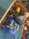
I crimped ring terminals to each conductor and connected them directly to the battery terminal hardware under the hood. I was able to connect the ring terminals to the battery terminal clamps so that it won't be any extra work at all to change the battery. I added an inline fuse to the positive wire just a few inches from the battery and installed a 20A fuse. Inside the car, I tapped the fusebox for an ACC switched power supply and used this to power a time-delay relay that I inserted into the hot leg of the new power supply wires and tucked them up under the glove box with a few zip ties.

The LTO battery charges to 16v at 9.0A, for a total draw of 144w, plus incidentals and efficiency losses. The new power supply should be able to handle this without any issues at all: it's all 12g wire with a straight shot to the battery that is ACC switched with a 40A time-delay relay. No more fiddling with the utility outlet and plugs that don't fit/hold as tightly as they should... No more worrying about the utility outlet wire being too thin- I'm guessing it is a maximum of 16g, more likely 18g. After all of this, I'm hoping that I'm done fiddling around and "fixing" things now!

This is what the EcoFlow utility plug looks like after it melted last week. It's a shame that it died, it was a pretty nice cable otherwise...
EcoFlow Plug.JPG
 
Nice setup.
This is how I'm going to rewire my Jeep and the rest of my family's cars, just need to find some time, too busy at work.
It'll be a lot easier for me because all of our cars have the battery in the cabin or trunk, so no need to go through the firewall.
You mentioned that you connected the power wires directly to the battery terminals.
Not sure about your specific car, but most modern cars have what's called a Battery Sensor on the negative terminal.
If this is the case with your car, it's best not to connect the negative wire directly to the negative terminal of the car's battery, but to ground it to the chassis.
Here's the interesting article and a quote from it:

https://www.samarins.com/glossary/battery-sensor.html

“If a car has a battery current sensor and additional electrical accessories are connected directly to the battery negative terminal, it may cause problems, because the electric current will bypass the battery current sensor and its readings won't be accurate. For example, the owner's manual for the 2019 Ford Explorer advises not to connect any electrical device ground connection directly to the low voltage battery negative post to ensure proper operation of the battery management system (BMS)”.
 
Last edited:
Good to be aware of, thanks! I know my 2019 Volvo has a pretty sophisticated BMS because it has two batteries and tons of "extra" stuff: active start-stop, heated seats, heated steering wheel, Nav, all kinds of stability/safety systems, etc, etc. When the battery is replaced, the BMS "counter" needs to be reset in the software so the care knows that you have a new battery, as the age of the battery impacts the charge rate. This is why pulling an extra 6-8A out of the fusebox in the trunk for the EcoFlow charge caused some issues...

My son's car is a 2014 Mustang GT which appears to have a much more simple electrical system (no nav, no "extra" screens, no start-stop, etc). I didn't see any kind of battery sensor on the negative terminal, it was just a few heavy wires bolted directly to the negative terminal clamp. One of these wires is a straight shot to the chassis for grounding about 10" away. The other wires appear to go directly to the starter motor and the under-hood fusebox. I just added the LTO charge wire directly to the negative terminal clamp.

The positive terminal has three separate red wires connected to it. One passes through a 100A fuse block, the second passes through a 200A fuse block and goes to the under-hood fusebox, and the third wire is just a straight shot to the starter motor (no fuse). I attached the LTO charge wire directly to the positive battery terminal before the fuse blocks. I figured that passing this extra current through either of the two large fuses would just be asking for trouble. There aren't any little "sensor wires" attached to the fuseblocks on the positive terminal.

I didn't see anything that looks like the monitor shown in the article that you linked on either battery terminal, but there does seem to be some active battery management going on. With the battery removed from the car, I connected my Topdon battery tester and it showed 100% state of health and 85% state of charge. 85% SoC seems to be a somewhat universal target state for an active BMS, so there is something going on there. I'll have to take another look at the terminals, but I don't recall seeing anything like what was in the article you linked.

If you are looking for a heavy power cable with lots of insulation for abrasion resistance, the one I linked above is very high quality. I was blown away when it arrived, it is a true 12g wire, the insulation is WAY thick (two layers), yet still nice and flexible.
 
Last edited:
Here are images of the Mustang battery terminals. I don't see any kind of current/voltage flow monitor like in the article that you posted.

The negative terminal in the image below is just a formed piece of metal that has two wires crimped onto the end on the right hand side of the image. The yellow ring connector is my addition and the new cable is zip tied to the existing cable to hold everything together and prevent wiggling.

IMG_10341.JPG

Below is the positive battery terminal. In the foreground (slightly blurry) is the nut that secures the clamp to the battery terminal. The red wire with the yellow collared ring terminal is the new LTO charging wire. This wire and the entire terminal assembly is normally covered with the red rubber boot that you see on the right. I've just pushed it to the side so I could photograph the terminal.

IMG_10343.JPG

Below is a side view of the positive battery terminal connector. The top wires that run down to the left are two non-fused wires that are crimped/bolted directly to the terminal hardware. I shared one of these connector points for the LTO battery. Below my connection point, you can see the two fused connections: 200A on the left and 100A on the right. There are no other sensors or wires connected to the fuse block to monitor current/voltage levels. The terminal harness is a single piece of metal from the terminal to the bolt that reaches the top of each of the fuses.

Given these images, I'm assuming that I'm in good shape by directly connecting the LTO battery pack directly to each battery terminal here.

IMG_10344.JPG

In the front view below, I've circled my newly installed positive LTO lead and the fuse in yellow. There are no "exposed" wires under the hood, everything is wrapped in the flame-retardant sheath and I've zip-tied everything down to existing wires to prevent stress and wiggling.

IMG_10345.JPG
 
Last edited:
Yep, there is no sensor, and it is perfectly fine to connect the power wires of the DVR battery directly to the terminals of the car battery, I would do the same.

Frankly, these new cars are way over complicated, and some systems, like Stop-Start for example, are just nonsense in my opinion, so I permanently disabled Stop-Start on my wife's Lexus.
 
Hmmm... Just noticed an interesting and unexpected behavior with my LTO battery. In my Volvo, I charge the battery pack from the utility outlet in the trunk. The charge rate is ~7A, so I'm looking at a maximum current power draw of about 112w (16v * 7A). My battery and camera have been behaving well since I put the battery in place a few weeks ago.

But today, I did something I haven't done before: I had the BMS app open and connected to the battery as I started the car. Before starting the car, the BMS was turned on and the app showed the voltage in the battery and no current draw (camera was off). When I started the car, the camera turned on and the BMS began reporting NEGATIVE current draw. It started at -2.0A, then over the course of about 6-8 seconds, it changed to -5A, then to -7A, then to -9A. Then it began decreasing toward zero amps, and then showed a 7A charge rate. This whole string of changes lasted about 10s or so. After the 10s, the charge rate held steady at about 6.9A to 7A. The utility outlet turns on/off with the car's ignition.

Is this simply the car's electrical system behaving strangely while the ignition starts up and the alternators starts charging and settles in to steady state operation?

Is this a sign that I should add a time-delay charging relay to my LTO box? Or would a backflow prevention diode take care of this situation? It seems that the LTO battery power is flowing INTO the car's utility outlet...

I was just surprised to see the BMS reporting such a large current draw for what seemed to be a longer period of time than I would have expected to see.
 
Just started the car again and made a few screen caps from the BMS app when I went to pick up my daughter. This time, the entire "settling in" process lasted only about 2 seconds (it was closer to 10s perviously). The cycle that I described above was at the end of the work day, so the car had been off for about 9 hours.

Here is what I saw this time. This is a total time span of about 2 seconds from ignition off/dashcam off (far left image) to steady state, engine running/dashcam powered (far right image) BMS power draw after starting the car:
BMS Current Draw.jpg

The alarming part is in the second screen cap (just a fraction of a second after starting the car) where it shows 174w of power draw from the battery! I presume this flow is going back into the car's utility port?? There is no way the dashcam is pulling this kind of power. Or is this just some anomaly of the charger board that feeds the BMS as it starts up and initializes?

I need to pull the battery out of the car and see how it behaves when connected to my AC powered 12v SMPS...
 
Last edited:
This is strange.

My 4S LTO battery is disassembled for configuration update to 5S, so unfortunately I cannot check it right now.

I don't think it's the car's electrical system so the time delay relay shouldn't matter.

The charger is a non-isolated type (as most Victrons and others) meaning all the grounds/negatives are directly interconnected.
However the charger’s positive is backflow protected, hence there should not be a backflow.
If for some reason backflow protection is not working, than yes the voltage will flow from 16V LTO to 12V car battery.

Try activating the ACC but not starting the engine (alternator) and see if there is a negative flow and if it is steady.
Hopefully 15A inline fuse will protect the car’s wiring, or you can replace it with 10A fuse for the test.
 
I did note that the ground side of the charger board is just a straight shot through the board: the ground input is always connected directly to the ground output. I also noted that the product description of the charger board indicated that it is backflow protected, thus an anti-backflow diode "shouldn't" be necessary.

The LTO battery pack has a 15A automotive fuse at the XT60 power input port AND another 15A automotive fuse between the charger board and the positive LTO terminal. I'm guessing that 5-10s of excess current flow won't be enough to blow the fuse (I'm assuming automotive fuses aren't fast acting). I'm using the EcoFlow charging cord in my car's utility jack and that also has a 15A fuse in it. Though, given the trouble I had in my son's Mustang, I'm contemplating changing the charging method in my Volvo. I'm a little reluctant to do the same level of hard wiring in my car as I still have an active warranty ;-).

Checking just ACC power (instead of starting the engine) might be revealing, I'll go check...
 
For safety, you can also limit the current in the BMS app.
Acts instantly.
 
Last edited:
Hmmm... Same behavior just switching on ACC and not starting the car. Current draw at zero with everything off. Current went negative immediately on activating ACC, then after a few seconds changed to about 7.2A of charge current.

I guess the next step is to open the LTO box and put a current meter on the positive leg that comes from the XT60 connector and see what it says.
 
It is too late now, I have to go to work in the morning, but I will try to temp assemble my 5S LTO tomorrow after the work to check it. (just charger + BMS + Battery, without relay and ups)
This is what my 5S looks like right now.
 

Attachments

  • IMG_7604.JPG
    IMG_7604.JPG
    513.5 KB · Views: 6
Ha! I used a sharpie to label the pots on my charger board with "V" and "C" for voltage and current adjust so I wouldn't mix them up, too ;). How are you planning to anchor the charger to the top of the battery?
 
.... How are you planning to anchor the charger to the top of the battery?
I don't know yet, maybe it will be double sided sticky pads about 10mm high to move away from the battery, or I can bolt it upside down to the top cover, but I will have to think about maintainability.
 
This hobby and my curiosity is costing me some money :)
Ha, my wife is already making fun of me for this "great" idea of a dashcam my son had for each of us last Christmas... Here we are in Sept and I'm still fiddling with wires in the car.


For safety, you can also limit the current in the BMS app.
Acts instantly.
Do you mean turning off the "charge" setting in the app? I'm not aware of another current setting in the app itself.

I was watching again as I started my car today. It seems that the high negative current lasts longer (8-10s) when the car has been turned off longer (9-12hrs). The behavior makes me think there are discharged power supply caps somewhere getting charged up. Not sure if these are the output caps in the charging board (unlikely since they are so small) in the LTO battery or these are caps somewhere in the car's electronics, which also seems unlikely because I can't really see a good reason for the car's utility port to have output caps in the wire path... I'll unplug the charge cord for now until I have time to diagnose what is actually going on.

I'm hoping this is just a "phantom" draw being reported as the charger board initializes and provides power to the BMS. I don't want to think about all of the things that can go wrong by backfeeding 200w into the car's utility outlet...
 
Last edited:
Aha! Just found the Maximum Discharge Current setting in the manual:


"When the battery pack is discharged, and the current exceeds the "maximum discharge current" and the duration exceeds the "discharge Over-current delay", the BMS generates a "discharge Over-current alarm" and turns off the discharging MOS. After the alarm is generated, after the time of "discharge Over-current relief", the BMS relieves the "discharge Over-current alarm" and turns on the discharge MOS again.

Examples include setting maximum discharge current to 100A, 'discharge Over-current delay' to 10 seconds, and 'discharge Over-current relief' to 50 seconds. When the discharge current exceeds 100A continuously for 10 seconds during the discharge process, the BMS will produce a 'discharge Over-current alarm', turn off the discharge MOS at the same time, remove the 'discharge Over-current alarm' 50 seconds after the alarm is generated, and turn On the discharge MOS again."


So, it looks like I could set the Maximum Discharge Current to something like 1-2A, the Discharge Over-Current Delay to 1-2 seconds, and set the Discharge Over-Current Relief to 10 seconds and that "should" prevent my problem of have -12A of backflow into the car...

I have to say, it's a bit concerning to see 200w moving INTO the car's system from the LTO battery... At least this isn't a problem with my son's car as I have a 6-8s time-delay relay and the LTO box is directly wired to his battery. I don't see any real issues with a few seconds of backflow from the LTO to the car's start battery.

I thought I remember seeing that the charger board had an anti-backflow diode built in, but now that I'm looking again, I'm not seeing it.
 
Last edited:
Curiosity for sure, but this is also a 25A max rated charger, so a little more powerful, and the inductor which is the hottest part of the charger looks more powerful as well (max inductor current is 30A).

It also has a low input voltage protection to protect the car battery, similar to my current 7S LTO boost converter/charger, this should prevent charging when the ignition is on but engine is not running.

And I hope the fan will work
 
I just tested my 5S LTO battery, to see if I can replicate your backflow issue.
The setup includes the Battery + JK BMS + Charger using Cigar Lighter Adapter (CLA) Cable.
The time delay relay, the UPS and the dashcam are not included.
Charger set to 13.5V (full charge for 5S config) and 8A.

Tested first on a bench using my power supply, and there is no backflow and negative amps, the BMS App shows 0A and as soon as charging starts it shows 7.9A within a second or so.

Then tested in my jeep and got exactly the same result, with ignition ON engine not running and with engine running.

Everything works as it should. No signs of negative current/reverse flow.

The only difference in my setup is that my LTO battery was discharged at about 10V which is lower than car battery.
I am charging it now to about 13.2V or about 95%, this is higher than car battery at about 12.5V, and I will repeat the test in my jeep tomorrow.
 
Back
Top