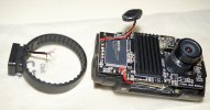
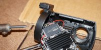
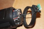
Mini 0806 (2nd Batch - Gear Best) - GPS issue, poor wiring [DIY Fixed]

I'd like to add that my GPS light did not turn on either so I tried to open it up and lo and behold, my cable was stripped at the same exact spot, and the same exact wire was torn from the solder. I re-doldered the wire back on and now the green light turns on immediately when I turn on the car. This fix was pretty easy if you know what youre doing... much better than to have to send this back to China and wait another 2 months for a replacement.

One thing I want to caution people on is that the clicking rotation motion is operated by a spring and ball bearing mechanism that are tiny. KEEP TRACK OF THESE TWO ITEMS. I spent the better part of an hour crawling on my carpet trying to find them.
 
It's my turn now. GPS was not working neither power from the mount.

Those wires are horribly tiny.
I was careful but those wires were completely off the board.
Looks like solder is real weak.

Also I forgot how everything goes back together.
Hopefully it'll be pretty obvious.
Wires are really short so it'll be a challenge to solder them, specially when the wire needs to go through the cover on it to rotate. Hmmm...

DSC01437-mini0806-wires.jpg
 
Last edited:
From top to bottom (as pictured)

Blue/Red (TX)
Red (5V)
Copper (GND)
Green (RX)

Looks like your "MXIC" chip is burned a little where they soldered the speaker wires on your unit as well, judging by the picture.
 
Yes, plug it into the fuse box. You have to use two the same fuses (ampere). I bought it at an auto supply store (Belgium). I don't use a hardwire kit. I also bought this (the bottom female connector, see photo) and connected it to the piggy back fuse thingy. The negative wire, is the ground wire, connected to the chassis of the car.

I don't think it's correct that you should use two of the same amperage fuses for that piggy back fuse thing. From what I understand, you should use a low amp fuse (1-5 A) for the dashcam and then the original fuse from the fuse box (which might be a 10A fuse).
 
From top to bottom (as pictured)

Blue/Red (TX)
Red (5V)
Copper (GND)
Green (RX)

Looks like your "MXIC" chip is burned a little where they soldered the speaker wires on your unit as well, judging by the picture.
Yes, that's how I have the wires lined up in the picture.
Too late tonight plus I need to DIY thin tip for solder as the tip I have is big enough to cover two joints.
 
I don't think it's correct that you should use two of the same amperage fuses for that piggy back fuse thing. From what I understand, you should use a low amp fuse (1-5 A) for the dashcam and then the original fuse from the fuse box (which might be a 10A fuse).
Using the original 10 amp or bigger fuse in the bottom and a 1 amp fuse in the top will be safest.

Detailed explanation:
The fuse is there to protect your device and cabling in the event of a failure or short circuit, the fact that it powers your device successfully does not mean that you car wont burn if a sharp piece of metal cuts through the cable insulation in a years time.

If the insulation gets cut by a sharp piece of bodywork or metal bracket then if you are using a 10 amp fuse with 2 amp cabling the cabling could catch fire and burn your car to it's shell, with a 2 amp fuse and 10 amp cabling everything will be fine.

So with a piggyback fuse tap device, use the original fuse in the bottom slot and a fuse that is smaller or equal to the rating of your cable and your device in the top slot. For a 1.5 amp hardwire kit, that normally means using 2 amp cable (5 amp will do fine) and a 1 amp fuse.

Unless you know how many amps the cars fuse socket can safely supply, you should assume that it can supply no more than the original fuse rating, so if you are piggybacking on a 10 amp fuse your second fuse should not be more than 10 amps. You should also ensure that the total load taken by both fuses is no more than the original 10 amps since with two 10 amp fuses pulling power you could then draw 20 amps from a fuse holder supplied by 10 amp cable (= fire). The easy way to ensure that is to fit the piggy back fuse tap the correct way around so that all the power has to go through the original fuse before some is tapped off to your device, that is with the fuse tap output cable on the supply side of the fuse box.
 
From top to bottom (as pictured)

Blue/Red (TX)
Red (5V)
Copper (GND)
Green (RX)

Looks like your "MXIC" chip is burned a little where they soldered the speaker wires on your unit as well, judging by the picture.

Do both covers need to be on the camera or can I just have the front cover with wire hole on it and put the other back cover after soldering wires?
I don't want to solder just to find the back cover won't go in the rotating mount attachment. :confused:

No time this morning so will work on it tonight after work.
 
So with a piggyback fuse tap device, use the original fuse in the bottom slot and a fuse that is smaller or equal to the rating of your cable and your device in the top slot. For a 1.5 amp hardwire kit, that normally means using 2 amp cable (5 amp will do fine) and a 1 amp fuse.

Could you clarify regarding the 2 amp cable? Is this the cable on the piggyback fuse tap device or you're referring to the cable on the hardwire kit?

You should also ensure that the total load taken by both fuses is no more than the original 10 amps since with two 10 amp fuses pulling power you could then draw 20 amps from a fuse holder supplied by 10 amp cable (= fire). The easy way to ensure that is to fit the piggy back fuse tap the correct way around so that all the power has to go through the original fuse before some is tapped off to your device, that is with the fuse tap output cable on the supply side of the fuse box.

I understand the goal, but not clear on the implementation to insert the fuse tap device the proper way. Since the leads on the device are the same, there's 2 ways to insert it into the fuse box and I always get confused what's the difference. Not clear what does "fuse tap output cable on the supply side of the fuse box" mean. Is there a drawing or diagram you can refer me to? Thanks.
 
Could you clarify regarding the 2 amp cable? Is this the cable on the piggyback fuse tap device or you're referring to the cable on the hardwire kit?
Both are going to get hot if too much electricity flows through them. You should choose the fuse to protect the lowest rated component in the system, almost certainly the hardwire kit. It's cable will be rated at least the same as it is. If you are adding any extra cable as an extension then make sure it is rated high enough, don't add 1 amp cable when you have a 2 amp hardwire kit and 2 amp fuse as your 1 amp cable can then get hot.

I understand the goal, but not clear on the implementation to insert the fuse tap device the proper way. Since the leads on the device are the same, there's 2 ways to insert it into the fuse box and I always get confused what's the difference. Not clear what does "fuse tap output cable on the supply side of the fuse box" mean. Is there a drawing or diagram you can refer me to? Thanks.
Since fuses don't have a correct way around, most fuse boxes don't label which side is supplying the electricity and which side is protected by the fuse so the only way to know which is the correct way around is to check with a multi-meter which side still has the power when the fuse is removed - the fuse tap cable should come out that side since it will then use both fuses.

Most fuse boxes will be able to supply far more current than needed anyway so few people bother but there is always the chance that a circuit will be supplied by a small relay or even transistor in the cars main computer, for example the interior lighting circuit in my car has soft on/off driven by transistor on an expensive circuit board, if you damage that then you will wish that you had checked!
 
Bad news. It's a brick now.
Spent over 2.5 hours trying to fix it with a burnt finger from soldering iron. :mad:
It was very hard to solder the wires as they are very close together and very tiny tips.
Finally, got them soldered but the camera didn't turn on after that.
Took it apart again and looked okay. Re-soldered to make sure.
No power, not even with charger port on the camera.
Took it apart and took the wires out.
Still no power.
Looks like either the chip overheated during soldering or something else.
So it'll go back and not looking forward to another mini.

I should have left it alone and used without GPS, would have made a nice rear camera. :(

DSC01438-small.jpg
 
Last edited:
What do you mean by "it'll go back"?
Meaning it'll go back to seller.

However, some good news.
I hate to give up so opened it again and re-soldered from scratch. It's almost midnight.
Now, it powers on and works via camera's charging port but still no power and no gps when connected to the mount.
I think the wires are just too thin and may have burnt the tip to make good contact.

At least now it's back to what it was, works via camera's port but not from mount's ports.

I can open the contacts on the mount and connect my own wires if I know what contact strip on the mount is what wire.
May be @Rayman.Chan can provide that schematic.
Edit: I can open the mount and trace the wires as they are color coded. Hmmm...

Existing wire is very short and fragile so replacing it as a whole will be better.
I think if the camera is twisted to either limits, the farther side wire will be too stressed and eventually break.
That wire needs to be little longer and stronger to give more room to rotate.
 
Last edited:
Meaning it'll go back to seller.

Interesting. Did the seller send you this 0806 for free and testing, or did you buy it yourself? I would have thought for a lot of electronic devices, once you open up the case and tinker with its internal components, you would void the factory warranty and the seller will not repair or replace it free of charge anymore.
 
Interesting. Did the seller send you this 0806 for free and testing, or did you buy it yourself? I would have thought for a lot of electronic devices, once you open up the case and tinker with its internal components, you would void the factory warranty and the seller will not repair or replace it free of charge anymore.
That's true but Rayman has allowed many here to open and try to fix without voiding warranty and many are successful in fixing the problem.
 
From top to bottom (as pictured)

Blue/Red (TX)
Red (5V)
Copper (GND)
Green (RX)

Looks like your "MXIC" chip is burned a little where they soldered the speaker wires on your unit as well, judging by the picture.

That order doesn't make sense now after opening the mount.
As you can see, TX is green not, blue/red.
I think that's why the camera didn't work as the wiring is wrong.
Not sure if that was messed up in the factory and soldered at wrong point on the board.

DSC01454-wiring.jpg
 
what happened to that?
Nasty looking after soldering and desoldering multiple times.

So on the board, how do I read label?
Is TX next to TX label or on the other side and next to TX label is RX wire?
 
Nasty looking after soldering and desoldering multiple times.

So on the board, how do I read label?
Is TX next to TX label or on the other side and next to TX label is RX wire?
Your second option.

I think you should be connecting TX to RX since the data transmitted (TX) from the GPS device needs to arrive at the receiver (RX) of the main PCB.

To power the camera you only need +5v (VCC) and GND connected. To receive GPS data you need a connection to the RX on the main PCB, I think from TX on the base.

I guess the EN (ENable?) is probably not used by the GPS base but will be with the Parking Guard Mount to indicate ENgine running.

I see.
I swapped the wires and now it's dead again.
It's not even working with camera's charging port anymore.
What a waste of time!
Wasted hours last night and today morning for nothing.
 
Back
Top