Mini 0806 Mount wiring confusion... green, red, copper, blue/red...

Sunny

Well-Known Member
Joined
May 31, 2014
Messages
5,095
Reaction score
1,739
Location
Colorado
Country
United States
Dash Cam
More than I can review. ;)
Okay, after my unsuccessful attempt to fix the wires that came de-soldered, I opened up the mount to replace the wires with something stronger.
Now I see there is enough wire there curled up.
It'd have made it much easier to solder had I pulled the wire little bit.
Anyways, I am confused on the labeling.
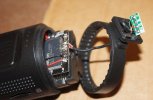
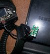
DSC01454-wiring.jpg
20150313_064524-wiring.jpg

On the board, it has
RX
GND
5V
TX
How do I read it?
Is TX the next solder joint or the one on the other side?

And reading the DIY thread, it's mentioned that,
Green is next to TX label on the board followed by copper followed by red and finally blue/red.

On the mount, the correct color and code are together.
TX is green.
GND is copper.
VCC is red. --> 5v
EN is blue/red. --> I suppose this is RX.

The suggested order in the DIY thread doesn't make sense whether I start green at TX on the board or on the other side.
If I start green next to TX, the next one should be red 5V, not copper as suggested.
If I start green on the other side, next to the other side is 5v that's correct as well as the GND after that but then the suggested order doesn't match because DIY thread suggests green should be next to TX marking and blue/red is the actual TX but the mount has green as TX. WTH???
Is the green colored wire soldered at TX by mistake in the mount instead of RX blue/red?

Thanks for clarifying before I start again on soldering these with new wires.
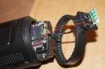

DSC01454-wiring-match.jpg

So should the TX/green wire be soldered on the other side of TX label or right next to TX label?
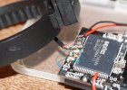
DSC01442-wiring-question.jpg
 
Those PCB solderings jobs must be done in such a tiny space that in home conditions without special equipment its easy to damage a motherboard.
I wish they would not solder wires to PCB but add a cables connector. This way it would be easier to handle ( troubleshoot ) some minor DIY jobs at home even for average Joe.
Maybe they will do the for batch 3 or 4? That would reduce defects in production.
 
Mine is still on a slow boat from China but it looks like it is very easy to open the mount without opening up the camera? Just two screws on the mouth? This defect is too much wire in the mount causing tension on the wire in the camera when rotated. This may be an easy way to check mine when it finally arrives.
 
Those PCB solderings jobs must be done in such a tiny space that in home conditions without special equipment its easy to damage a motherboard.
I wish they would not solder wires to PCB but add a cables connector. This way it would be easier to handle ( troubleshoot ) some minor DIY jobs at home even for average Joe.
I upgrade crossovers and even amplifiers sometimes and had great results for years.
So I don't consider myself average Joe but I guess this experience with a dead camera made me an average Joe. :(
 
Cable connectors are good thing for things that you expect buyers need to work on frequently like computers where upgrades are normal thing.

cable-connector-500x500.jpg


However, dashcams are meant to set and forget so not needed.
This is an one off problem but I agree cable connectors would be so much to take apart and fix without damaging PCB board or chip with heat during solder.
 
Mine is still on a slow boat from China but it looks like it is very easy to open the mount without opening up the camera? Just two screws on the mouth? This defect is too much wire in the mount causing tension on the wire in the camera when rotated. This may be an easy way to check mine when it finally arrives.
If you have any issue with it, I suggest returning it unless you are really good at soldering or at least make sure you can return it after you try the fix and if it doesn't work.
 
As daft as it sounds console repair companies are usually great at soldering things like this - usually because they're used to soldering tiny little chips into consoles!
 
As daft as it sounds console repair companies are usually great at soldering things like this - usually because they're used to soldering tiny little chips into consoles!
Soldering is one issue and wire pinching another.
In my unit, the wire was okay but all the individual wires were disconnected.
That explains why it was not pinched as it moved freely.
But for the ones that have wires connected, there is a high chance of pinching the wires when rotating.
That chance can be avoided with a small tube to hold the wire past the housing to empty space.
Right now, the wire can get in between the housing as there is just a hole from the mount.
Maybe that's something @Rayman.Chan wants to add in future versions.
 
Last edited:
I would be most unhappy and return it...

Kind of reminds me of visiting a whorehouse and having to make your own $140 hole to be able to use it !!!
Hmmm... where is that whorehouse? :D

I really wanted this mini0806 to work as I was planning on using it in the rear window instead of the big G1WH that's there now.
It was sick and needed a surgery but it died after the procedure. ;)
 
Last edited:
I upgrade crossovers and even amplifiers sometimes and had great results for years.
So I don't consider myself average Joe but I guess this experience with a dead camera made me an average Joe. :(

Dont get me wrong, I did not consider you an average Joe, you for sure have courage and experience to mess around with soldering and fiddling. I meant dozens ( 100's ? ) of other people who might experience same issue like you and want to have a simple DIY fixing solution.
 
As I mentioned in the other thread, TX and RX are swapped between the areas. The "TX" on the little mount area goes to the "RX" on the main board. VCC goes to 5V. GND goes to GND. "EN" goes to "TX" on the main board. You have everything soldered in the right place in your picture, though either that is a lot of flux or you burned the heck out of it.
 
Time for a continuity tester to find out what is shorted out?

I think those thin wires are designed to be extra flexible right up to the solder joint so that they don't suffer metal fatigue at the joint with constant movement of the rotation mechanism and so should be much more reliable than using a connector. I think they are designed to be soldered in place with the coloured insulation still in place, not sure your solder joints are quite what was intended!

With the right soldering iron, small enough tip and magnifying glass mounted over it, soldering should be reasonably easy and neat, use too big a tip and it will become very difficult and untidy - you should probably blame your tools!
 
I think they are designed to be soldered in place with the coloured insulation still in place

That's exactly how I did mine and it works great. I used the existing solder that was already there (there was plenty). It's also important to make sure you don't accidentally create a solder bridge between two of the wires (if your solder iron tip is not small enough, it will be hard to avoid it). If you bridge two of the connections you might make the camera not function even when it is plugged into USB.
 
As I mentioned in the other thread, TX and RX are swapped between the areas. The "TX" on the little mount area goes to the "RX" on the main board. VCC goes to 5V. GND goes to GND. "EN" goes to "TX" on the main board. You have everything soldered in the right place in your picture, though either that is a lot of flux or you burned the heck out of it.

Yes I thought so but the green wire is TX in the mount connection and that's supposed to be on the other side of TX label on the board, blue/red should be on the solder joint next to TX.
I think there is something weird going on.
My 1st try was cleaner then the camera didn't power on so I tried to clean the solder joints thinking it may have a short but that's not the case.
After 3rd time soldering, the top layer of the board in between the joints is gone so it looks a mess.

Time for a continuity tester to find out what is shorted out?

I think those thin wires are designed to be extra flexible right up to the solder joint so that they don't suffer metal fatigue at the joint with constant movement of the rotation mechanism and so should be much more reliable than using a connector. I think they are designed to be soldered in place with the coloured insulation still in place, not sure your solder joints are quite what was intended!

With the right soldering iron, small enough tip and magnifying glass mounted over it, soldering should be reasonably easy and neat, use too big a tip and it will become very difficult and untidy - you should probably blame your tools!
I agree, not having right tools maybe part of the problem but I did use very fine soldering tip, no magnifying glass though but I still have good vision.

The wires are flexible and that's good thing but they are very fragile as well.
I think for rotating mechanism like these, the connection should be on the housing itself that doesn't move anything on the board.
Anytime you have something that's pulling and stressing wires or connectors on the PCB board, of course it'll fail sooner or later.
There should be something to prevent those wires from pulling like what they do on PC boards where they have a knot through a hole so all the tension is held on by the knot, not by the soldered joints.

Anyways, it's done.
I'm not spending any more time on this.
I took all the mount's wires off the board and still it's dead.
When I connect to charger, I feel it's heating but it never turns on.

I like it's design and would have loved to use it.
Hopefully, another similar kinda discrete design lands on my lap soon.
 
That's exactly how I did mine and it works great. I used the existing solder that was already there (there was plenty).
I think the insulation must act as the flux because with normal wire that wouldn't work until you added some extra solder with flux.
 
Yes I made sure only the small tip doesn't have insulation as that's what they had anyways.
Very frustrated with myself as I thought it was an easy fix but failed and specially when soldering is nothing new to me. :(
 
Actually though it sounds completely backwards with these small solder joints and SMD in general you want a bigger soldering tip. Reason being is you want to transfer that heat as quick as possible and get it the hell away before you damage the board or components. I know it doesn't seam right but it's what has always worked for me, of course your mileage may vary depending on technique.
 
Back
Top