Mobius support thread and Tech Guide (post all problems/help requests here) Read posts #1-8 first

GJHS

Well-Known Member
Joined
Nov 21, 2013
Messages
2,108
Reaction score
1,367
Country
United States
Dash Cam
Mobius A & C, SJ4000, M10, Mini 0806, Innovv C3,4, Xiaomi Yi
As suggested by @Isoprop, I have started a support thread for the Mobius. Here you will find useful information and support for the Mobius, as well as solutions to many situations. This is your go to guide for any questions or problems so:

Please post all support requests and problems here, do not start a new thread. Read posts #1-8 first. If you can't find your answer there then post your question or support request :D

The information found in posts #1-8 come from the RC Support Thread and is current as of Feb 12, 2014 (http://www.rcgroups.com/forums/showthread.php?t=1904559). The authors of this information are Tom Frank and Isoprop to whom we owe a huge Thank You for all their support of this camera and it's users.

If you find any mistakes, please send me a private message, as not to waste space here.
 
Last edited:
Mobius ActionCam Vendors and Specs

The Mobius, by the developer of the highly successful #16HD "808-style" keychain camera, is a logical progression to the more capable 1080p level of video hardware. The features that made the #16 such a hit, namely small, light, configurable, great video, and low cost are being extrapolated and expanded to match the capability of the new hardware. The firmware will take many months to mature and incorporate all the capabilities of the new hardware, but the developer is actively pursuing this goal while watching this thread for user feedback on issues that might need fixing.

Vendors

You are advised to only buy your Mobius from a developer-verified source. The following web stores have been verified by the developer as selling the real Mobius camera, replacement parts and accessories with a commitment to customer satisfaction, both before and after a sale, if any problems are found when the hardware is put into service and not caused by user abuse, crash damage, etc.

Direct Sellers:China: eletoponline365; digitalele889Re-sellers:China: HobbyKing (Hong Kong); BangGood; Singapore: Drone Matters

U.S.: BuyMobius.com, a.k.a. novotm (MA); Massive RC (FL); SPYTEC (NY); ReadyMadeRC (OH); BangGood-US warehouse (CA); JooVuu-US warehouse (PA); HobbyKing-US Warehouse-East (AR); HobbyKing-US Warehouse-West (WA)

Canada: Great Hobbies (PE, ON, AB) Europe: BangGood (UK warehouse); Webbex (UK); JooVuu (UK); Pakatak (UK); ; Mobius-Cam (NL); Revotech (CZ); Car Black Box (PL); Mobiuscam (RU)

Non-verified sellers may be selling fake imitation cameras at seemingly bargain prices, and you should be wary of buying from them.

Memory Cards
Class 4 memory cards from popular manufacturers provide the best compatibility with this camera and are recommended. Class 6 and Class 10 cards, at best, do NOTHING to improve the camera's video and cost more, and at worst, they may not work properly! ALL MEMORY CARDS should be formatted using the camera's internal formatting routine for best compatibility!
. If you are uncertain about what kind of memory card to buy, order one from the camera vendor when you place your order.

wol_error.gif
This image has been resized. Click this bar to view the full image. The original image is sized 1024x849.
a5889466-181-Mobius%20Actioncam.jpg


Circuit Board

The circuit board has a reset button and easy disconnects for the battery and CMOS ribbon cable. The charging and external communication port is a standard 5 pin mini-USB socket. PLEASE NOTE THIS USB POWER SUPPLY ALERT. Standard microSDHC cards up to 32GB are accepted for recording. Class 4 cards should work fine and are recommended. The CMOS imager and DSP chips used in the camera are confidential at this point at the developer's request. The stock 520 mAH lipo battery can power the camera for approximately 80-90 min.
wol_error.gif
This image has been resized. Click this bar to view the full image. The original image is sized 1600x1200.
a5889731-87-P6280045.jpg

wol_error.gif
This image has been resized. Click this bar to view the full image. The original image is sized 1600x1200.
a5889732-55-P6280048.jpg


Lens

The original lens, now being referred to as "Lens A" is a mid-AOV lens with some fisheye distortion in the 1080p frame size, but less than the wide angle D lens on the #16. When the camera is in 720p-60 fps mode the 1280 x 720 image is sub-sampled from the center of the wider 1920x1080 frame image, so the video FOV is proportionally less, but so is the fisheye distortion. In 720p-30fps mode, the camera keeps the wider FOV of the 1080p mode, but scales the imaged down to 720p frame size (detail loss is very minimal). Vignetting and focus drop off at the edges are negligible. I measured the actual FOV of the video frame width to be nominally 85 deg. at 1080p and 720p-30fps, and 46 deg. at 720p-60fps settings, and based on those, I estimate the AOV of the standard lens to be around 110 deg.

A wider AOV lens, referred to as "Lens B" is now available (details here), and more high quality/nominal cost lens alternatives are continually being sought. The CMOS module has a "standard" 12M x 0.5 thread, so it can accept other third party lenses if a user can find a suitable one.

The CMOS imager and its ribbon cable attach to the lens module via two machine screws, making it possible to replace just the CMOS imager if necessary. The lens module is made of light metal with a set screw to hold the threaded lens at the ideal focus point, yet allowing it to be easily released for focus adjustments if necessary. The metal module also acts as a heat sink for the CMOS imager.
User Toggled Functions
Camera functions are an expanded version of the #16 functions. The development of functions and user settings for the camera will be ongoing following the initial release, all of which will work in the camera when updated FW is loaded. The initial release FW includes:

•Two user selectable video modes, toggled by the mode button after power up. Either mode can be set to record 1080p-30fps or 720p-60fps or 720p-30fps. The video format is .MOV with H.264 compression codec, and the camera can record sequential clips with a one sec. overlap, so there is no lost video.

•Three movie quality settings (Super, Standard, and Low), which will vary the recording bit rates suitable for the user-selected frame size and frame rate. The Super setting (called the "High" setting in the GUI) with 1080p-30 fps video gives an approximate average total bit rate around 18,000 kbps with a high detail and motion scene. The Low setting with 720p-30 fps video gives approximately 5,800 kbps on the low end.

•Five video recording cycle time settings will be 3, 5, 10, and 15 min. plus "Max", all of which will stop/save/continue. The Max setting will record until the 4GB files size limit is reached unless the memory card runs out of space or the battery power is removed. The actual Max recording time will vary dramatically accord to the users settings for frame size, frame rate, and movie quality. The 4GB file limit can be reached in less than 30 min. with 1080p-30 fps video set for Super quality.

•Loop Recording will continue recording when the card fills up by deleting the oldest clip on the card to make room. This mode requires either a 3 or 5 min. clip length setting to work. Pressing the mode button while a recording is in progress in this mode will tag the file as write protected when it is saved, so it won't be overwritten. The file can be manually deleted, though.

•Movie Flip (180 deg. rotation) will record a video right-side up when the camera must be mounted up-side down.

•Movie Sound allows turning off the sound and eliminating a sound track from a video file to save file space when no sound is wanted.

•Photo capture mode with frame sizes of 2304x1536, 1920x1080, or 1280x720 (no up conversion).

•Time Lapse photos with delays between images of .25*, .5*, 1, 2, 5, 10, 30 and 60 second intervals.
* Note: The settings below 1 sec. require a photo frame size of 1920x1080 or smaller, and they will not have a date stamp even if it is turned on.

•Recording LED toggle flashes the recording mode LED on the top and rear of the camera.

•Movie/photo time stamp toggle

•Power on button delay (to prevent premature activation while handling)

•Auto-record when power to the camera is applied (useful for car recorder use - no button presses needed.)

•Charging on/off toggle when plugged into a USB data port (useful for some external USB devices)
•TV out (PAL or NTSC), which includes a playback mode with audio.

•TV display ratio (4:3 or 16:9)

•GUI program for Windows OS for easy setting of the parameters as well as updating the firmware and the GUI program itself.
 
Last edited:
Firmware and Camera Configuration Settings
Camera Configuration and Firmware Information


It is strongly recommended that users with Windows PCs always use the graphical user interface (GUI) program to change camera settings and update firmware.

This page has an overview of the current configuration setting information and download links for the instruction manual (user guide) and Windows GUI software authored by Isoprop.

This page has download links for Android mobile device applications authored by therau2000.

New firmware and user settings can be loaded into the camera manually as a last resort (see below), but it requires specific file editing and handling procedures as well as multiple button press sequences on the camera. It is easy for user errors to cause these updates to fail! Also, there are numerous camera settings, some of which conflict with each other if both are toggled on at the same time. The GUI program will not permit these conflicting settings to be set so will eliminate all of these user error possibilities, so please do yourself a favor and use them.


Optional Manual User Configuration Setting Procedure

If a GUI tool is not available for your computer or you would rather just edit the configuration text file manually, it's easy to do, just follow these steps exactly:

1. Download the camera's configuration file to the flash card in the camera (HOLD DOWN MODE BUTTON, THEN ALSO HOLD DOWN POWER BUTTON UNTIL LED ACTIVITY STOPS).

2. Turn the camera on, connect it to your PC, and access the camera root directory when it goes into the "removable disk mode".

3. Open the "SYSCFG.TXT" config text file with a simple (ASCII) text editor (e.g. the familiar "Notepad" text editor for Windows users). The file will look similar to this date time=[2013/06/28-21:33:34];date time setting,format yyyy/mm/dd hh:mm:ss

Video Mode 1 resolution=[0];Movie resolution setting,0:1080p,1:720p
Video Mode 1 Frame Rate=[2];Movie frame rate setting,1:60fps (only for 720p), 2:30fps
Video Mode 2 resolution=[1];Movie resolution setting,0:1080p,1:720p
Video Mode 2 Frame Rate=[1];Movie frame rate setting,1:60fps (only for 720p),2:30fps

Photo Mode Capture Size=[0];set photo size,0:2304x1536,1:1920x1080,2:1280x720
Set Time Lapse Shooting=[0],0off,1:0.25s,2:0.5s,3:1s,4:2s,5:5s,6:10s,7:30s,8:60s

Movie cycle time=[2];movie cycle time,0:3 minutes,1:5 minutes,2:10 minutes,3:15 minutes,4:max to 4G byte,
Movie Loop Recording=[0];set loop recording on or off,0Off,1On,
Time stamp=[1];set date/time stamp on or off,0Off,1On,
Movie sound=[1];set movie sound,0:mute,1On,
Movie Flip=[0];set movie rotate,0Off,1On,
Movie quality=[1];set movie quality, set movie data rate,0:Super,1:Standard,2:Low,
Movie high dynamic range=[0];set movie high dynamic range,0Off,1On,

Power on=[1];set system power on time,0:delay,1:fast
Power off=[1];set system auto power off time when system pending,0Off,1:30 seconds,2:1 minutes,3:2 minutes,
Auto Record=[0];set connect or disconnect with power to start or stop video recording automatically,,0Off,1On,
LED=[1];set LED flicker when recording,0Off,1On,
Charge from USB Host=[0]; when connecting with USB host, charge camera or not,0Off,1On

TV out=[0];set Tv out,0:NTSC,1PAL,
TV Display Ratio=[0];set display ratio,0:4*3,1:16*9

{TLCAM MOV:2013/06/25 v0.32}
{LDTLCAM,v001}Note: Values used by the camera shown bolded in the square brackets. Functions shown may vary with firmware updates, but manual editing is similar. Text in curly brackets at the bottom show the firmware and boot loader versions in the camera.4. Replace any number(s) in the square brackets with any valid alternate setting number, shown highlighted to the right of each function. For the date and time, don't delete the dash (-), slash (/), or colon :)) marks or add any spaces or invalid numbers. You can keep the camera's current date and time if you use a question mark (?) for each number, i.e. [????/??/??-??:??:??] will keep the camera's current date and time.
NOTE: Except for certain functions which cannot co-exist, invalid numbers or other characters in the square brackets has not shown to cause serious problems. The camera appears to ignore them or switch to default values.5. Save the revised file back to the memory card root directory, but do not change the file name.

6. Upload the revised configuration back into the camera. The same key-press sequence used to download the configuration from the camera will also upload it to the camera.

7. When the LED turns off, you're done! The new configuration will be in the camera and the config file will be automatically deleted from the flash card. You may check the flash card to confirm this if you wish.


Firmware

You are strongly advise to ALWAYS use the GUI tool for all camera firmware changes (see above). The GUI will determine if your camera firmware is out of date, download the latest firmware if you agree, and install it for you, taking all the potential for user error out of it.

The firmware development and refinment is a continuing process, and the most recent OFFICIALLY RELEASED versions will be kept attached to this post as downloadable zip files. Any problems found with the Released Firmware should be reported to me via PM. Note: The different firmware will ALWAYShave the same name... FWTLCAM.BIN, which is necessary for the camera to identify it as firmware to be installed. When you un-zip the attached firmware archive file, the firmware FILE will be in a named FOLDER so you can tell at a glance which firmware file is in the folder. When preparing to install the firmware as detailed below, make sure to copy the firmware FILE (FWTLCAM.BIN) and NOT THE FOLDER itself to the memory card root directory. The camera will not find the firmware if it's in a folder. I keep old, obsolete firmware in case anyone needs a copy (PM me with your email address).

NOTE: BETA TEST firmware is created as part of the on-going development and is sometimes released to selected users for testing only. It is NOT officially released firmware and it may contain bugs, so is NOT intended for general distribution. .

The Mobius only uses MOV format firmware.

The most up-to-date firmware (and bootloader, if applicable) file is available for manual download at the bottom of this page.


Optional Manual Firmware Update Procedure

The following procedure is for manually updating your camera firmware. It is not necessary to do this if you can use the Windows GUI configuration tool (see above). It will determine if your camera firmware is out of date, download the latest firmware if you agree, and install it for you, taking all the potential for user error out of it. You are strongly advise to ALWAYS use the GUI tools for all camera firmware changes.

ALERT:

    • READ THE UPDATING INSTRUCTIONS FULLY BEFORE STARTING
    • DO NOT BEGIN UNTIL YOU UNDERSTAND EACH STEP
    • DO NOT SKIP ANY STEPS
1. Download the firmware .zip archive file and un-zip it. Copy the actual firmware file (always named FWTLCAM.BIN as noted above) from it's identifying folder into the camera's flash card root directory (the one that opens when the camera connects as a removable drive). This can be done with the card in the camera connected to the computer as a Removable Drive, or externally in a card reader. But do NOT rename the file. If you do, the camera will not install it!

2. Disconnect the camera and turn it off.

3. Insert the flash card containing the new firmware file into the camera (if not already in the camera).

4. Press the Power button until the BLUE LED turns on and begins to flash. RELEASE THE POWER BUTTON AS SOON AS LED FLASHING BEGINS! If you keep pressing it longer, you may turn off the camera before the update process is done. DO NOT PRESS ANY BUTTONS WHILE THE INSTALLATION IS IN PROGRESS (about 20 sec. to complete)

5. To confirm the firmware is being loaded into the camera, the BLUE LED will continue to blink during the upload process.

6. When the FW installation is complete, the BLUE LED will turn off for about 2 sec. and the YELLOW LED will then turn on solid, indicating the FW file is has been automatically deleted from the memory card.

7. You're done! The camera will be in the normal start-up standby mode ready for use.
 
Last edited:
FREQUENTLY ASKED QUESTIONS (FAQs) - under construction

Battery and CMOS/Lens Maintenance

1. Opening the case

The case has a top and bottom piece held together by two screws on the bottom front corners and two interlocking tabs/lugs on the back. Remove the two screws, lift the front of the case slightly, and push it towards the back (away from the lens) to remove the bottom piece and expose the circuit board.
wol_error.gif
This image has been resized. Click this bar to view the full image. The original image is sized 1600x1200.
a5886024-147-pic%201.jpg

wol_error.gif
This image has been resized. Click this bar to view the full image. The original image is sized 1600x1200.
a5854910-72-pic%202.jpg


There are three tiny screws securing the circuit board to the case top, but you will never need to remove these for normal maintenance.
wol_error.gif
This image has been resized. Click this bar to view the full image. The original image is sized 1600x1200.
a5854911-233-pic%203.jpg


2. Replacing the battery[/U]

The battery simply plugs into socket on the circuit board, and it has a key on the plug so it cannot be plugged in with wires reversed. The plug can be quite hard to remove, so a slight side-to-side rocking action with a thumb nail or NON-METALLIC tool in the gap between the plug and circuit board socket can help free it without exerting excessive force on the circuit board. Note the circuit board is long and narrow on that corner, and that portion is not secured to the case top when the bottom half is removed. Apply a little pressure with your thumb on the circuit board so it doesn't flex when removing the battery plug. NEVER PULL ON THE BATTERY WIRES to remove the plug! Plug in the new battery, re-position the cell and battery wires, and replace the case bottom when done.
wol_error.gif
This image has been resized. Click this bar to view the full image. The original image is sized 1600x1200.
a5854912-138-pic%204.jpg
 
FREQUENTLY ASKED QUESTIONS (FAQs) - under construction

3. Replacing the CMOS imager module

NOTE: The camera battery should be removed before doing this (see item 2., above)! The pictures referenced below incorrectly show the battery still connected!

The CMOS module is press fit into a ribbed securement structure on the case. Because the CMOS ribbon cable is very short and can be damaged easily, it's advisable to first slide the ribbon cable from it's socket before the module is extracted. The ribbon cable slides into a socket on the circuit board and is clamped in place by a hinged clamping tab.
wol_error.gif
This image has been resized. Click this bar to view the full image. The original image is sized 1600x1200.
a5855106-203-pic%205.jpg


The cable is released for removal by gently lifting up on the aft edge of the clamping tab with a thumb nail or NON-METALLIC tool, such as a toothpick.
wol_error.gif
This image has been resized. Click this bar to view the full image. The original image is sized 1600x1200.
a5855107-229-pic%206.jpg

wol_error.gif
This image has been resized. Click this bar to view the full image. The original image is sized 1600x1200.
a5855108-13-pic%207.jpg


Gently slide the ribbon cable out of the socket with a NON-METALLIC tool such as a toothpick.
wol_error.gif
This image has been resized. Click this bar to view the full image. The original image is sized 1600x1200.
a5855109-174-pic%208.jpg


Now the CMOS module can be extracted from the case, but it is a very tight fit and should be done carefully. I find the best method is to use a tool as a lever to just slightly lift one side of the module at the screw lug A strong (e.g. metallic) tool may be needed for this, and can be used without getting close to any circuitry if applied at the side of the module near the edge of the case. Once the edge of the module is lifted, the module can be easily removed with your fingers. Just be careful to not grab the ribbon cable.
wol_error.gif
This image has been resized. Click this bar to view the full image. The original image is sized 1600x1200.
a5857015-202-pic%209.jpg

wol_error.gif
This image has been resized. Click this bar to view the full image. The original image is sized 1600x1200.
a5857016-223-pic%2010.jpg


Replacing a module is slightly different. First, note that your module has some metallic tape on the underside. Do not remove this tape because it's purpose is to conduct heat from the metal CMOS back plate to the metal module housing which then helps cool the CMOS imager. But do look to be sure the tape is aligned on the module and does not have any creases or folds that can keep the module from seating fully in the case.
wol_error.gif
This image has been resized. Click this bar to view the full image. The original image is sized 1600x1200.
a5857129-3-pic%2011.jpg


Next, with the locking tab lifted, gently insert the ribbon cable into the circuit board connector, making sure it is fully inserted. It's a snug fit and needs to be inserted straight with maybe a slight side-to-side rocking motion. DO NOT force it. When in place, close the locking tab to secure the ribbon.
wol_error.gif
This image has been resized. Click this bar to view the full image. The original image is sized 1600x1200.
a5857130-218-pic%2012.jpg


Now position the module over it's seat in the case, allowing the ribbon cable to bend naturally. DO NOT force a sharp bend in it. When in place, push the module into the case slot by pressing on the side lugs. DO NOT press on the ribbon cable area on top of the module. It's a very snug fit, and a slight rocking side-to-side rocking motion may be needed. Make sure the lens is centered in the case opening and replace the case bottom.
wol_error.gif
This image has been resized. Click this bar to view the full image. The original image is sized 1600x1200.
a5857131-61-pic%2013.jpg


4. Refocusing or Replacing the Lens in the CMOS module

This is now an easy task. The threaded lens is secured in the module with a tiny set screw which requires a 1mm (I think) Allen hex wrench to loosen.
wol_error.gif
This image has been resized. Click this bar to view the full image. The original image is sized 1600x1200.
a5857193-162-pic%2014.jpg


To refocus the lens, simply remove the case bottom, mark the initial position of the lens with a thin line of paint across the lens threads and module base (optional-for future reference only), then loosen the set screw until the lens can be rotated in the housing. When facing the front of the lens, turning it to the left will move it further away from the CMOS and move the prime focus closer to the camera. The reverse will do the opposite. The lens should turn easily once the set screw is loosened enough, but there are small notches in the lens front rim to aid in turning the lens if needed. There should be enough room in the case to make moderate focusing adjustments without having to remove the module or circuit board from the case. Focusing can be done in web cam mode while viewing the image on a monitor, or by trial and error still or video shots noting the lens position for each and comparing afterwards. Its been claimed that still images of the same scene will have the largest file size when the camera is in best focus, though I prefer a visual indicator and have not tried to confirm this. The standard lens has a large depth of field, and images should appear as sharp as the lens is capable of from about 2 ft. out to infinity when in good focus. When the lens is focused to your requirements, simply re-tighten the set screw and replace the case bottom.

To completely replace the lens, you will need to remove the module from the case (see item 3., above) to allow enough room to completely unscrew the lens from the module. Then replace the lens, reseat the module, and replace the case bottom.
 
mSetup - the Mobius ActionCam setup utility and User Guide
This is the original Mobius GUI which I created in co-operation with the developer and Tom. Click HERE to download.

The program is a native Windows application specifically written for the Windows operating system (XP and above) and does not require any 3rd party runtime system, for example Java or .NET, to be installed. The simple and extremely user-friendly program is fully plug-and-play and includes an integrated User Manual.

The software is also compatible with all plug-and-play versions of the Mobius' little sister, the very popular #16.

The software will also identify all unknown USB cameras and devices with a capacity of 64GB or less. So, if the GUI doesn't recognize your camera, you don't have a #16 or a Mobius ActionCam!

You can take a peek at the software even if you don't yet have the camera. You can click on all the buttons, but they will be greyed-out until a supported camera is connected. The integrated help may also be useful.

Remember that you can resize the dialog by dragging the gripper at the bottom right corner if you prefer a smaller image. The dialog fonts will automatically be resized to fit.

The latest GUI software configuration tool together with the latest instruction manual (User Guide) may be downloaded by clicking on the link above or on one of the images below.

I strongly recommend that you enable automatic program and firmware updates so you always benefit from the latest available tools. This is specially worthwhile during the first few weeks after the initial release.

Here are some screenshots of the GUI (Graphical User Interface)


... you can set your own parameters and download new versions and format the camera's card


...and of course you can set your own colors for the program


...and lots of useful information too
 
The definite Guide to Power connectors, charging, and other power related questions
Mobius ActionCam


This guide is designed as a reference for the most common power-related questions and is thus fairly long. However, I hope you will find the answer to your question.

This post will be kept up to date.

Description
The Mobius ActionCam will run for about 80 minutes from a new fully charged internal battery. Recording in cold weather will drastically reduce the recording time.
Since you can't physically turn the battery off, the battery will always drain in order to keep the clock running. I don't know how long it will take to completely drain the battery, but I would expect a year, most probably much longer.

The camera can be configured either manually by editing an ASCII text file or much more conveniently by using the mSetup program (see post #6).
Recording without sound will give slightly longer recording times. Likewise, recording with a low video data rate will slightly increase the recording times. The recording indicator (flashing LED while recording) has no noticeable effect on the recording times. The recording indicator can be turned on or off in the configuration utility / text file.
The camera always records "clips" of a given length. The clip lengths can be set in the configuration utility / text file (see above). If the "Max." value is set, the camera will record clips with a length of 4GB. After the camera has written a clip, it will automatically create and record a new clip. This procedure will be repeated until the battery reaches a given threshold (runs out of power) or the flash card is full. If the camera is configured for loop recording, the oldest clips will be overwritten and recording will continue until there is no more internal or external power. There will be a 1 second overlap of two consecutive clips. The camera supports SD/SDXC cards formatted in FAT32 or exFAT and supports cards up to at least 64GB, most likely up to the exFAT limit of 512 terabytes.

Internal battery
The internal battery is a lithium polymer cell (LIPO), which, when fully charged, has a capacity of 4.2V. The camera will turn off when the battery voltage reaches approx. 3.5V.
The battery is user replaceable and comes with a tiny 2-pin connector. Since a connected external USB power supply will always supply more power than the camera functions require, the internal LIPO will be charged even when using the camera in Disk Mode, Webcam Mode, or Recording.
Battery protection circuitry is built into the camera. For this reason you should not replace the internal battery with another type of battery (for example Li-Ion). It is, however, possible to connect an external LIPO 1S battery in place of the internal battery but it should be recharged using an external charger.
The built-in charger circuitry is designed to charge a 520mAh LIPO (603030). A depleted battery will take between 2 and 2.5 hours to fully charge with the camera turned off. The green LED will be extinguished when the battery is fully charged. It is safe to assume the battery is fully charged after 2.5 hours even if the green LED is still lit.
You should never connect a second battery in series. Doing so will destroy your camera because the voltage is the sum of all the battery volts.
You should also not connect batteries in parallel unless they have been properly "balanced" by an external charger. If the cells are not at the same state of charge, the higher charged cell(s) will try to charge the lower charged cell(s) with no current limit. This could damage the cells and cause dangerous overheating of cells and wiring.
If you replace the internal battery with another source of power (battery, charger, etc.) the supplied voltage must not exceed 4.2V (5V is not permitted on the battery connector). Doing so may initially work but will over-stress other components and will most likely lead to premature camera failure. If you must connect a 5V supply to the battery connector, then use a small diode (e.g. 1N4001) wired in series in the positive line. This will drop the voltage by about 0.7V. You obviously have to connect the diode correctly or no current will flow!

Using an external single cell LIPO in place of the internal battery
Some users my prefer to use a larger single cell LIPO in place of the standard one. This is possible so long the internal battery is never connected at the same time. You should note, however, that charging a larger battery using the Mobius' charging circuitry will take a very long time. Also remember that every time you disconnect the battery from the board, even very, very briefly, the internal clock will be reset.

The USB cable
A standard mini USB cable has +5V connected to pin #1 of the camera's USB socket and -V (ground / earth) connected to pin #5 of the camera's mini USB socket.
On a standard mini USB plug the two center wires (Pin #2 and Pin #3) are the data lines and are only used when the camera is connected to a computer. They are not used when the camera is connected to an external power source such as car battery charger, external wall charger (mains charger), external USB power pack etc.
The camera "tests" the data lines as well as pin #4 to determine the connection type.
The camera can be operated normally using external USB power with the internal battery disconnected.
Pin #4, which is sometimes called Pin x, will switch the camera into AV-out mode (TV-Out) when connected to ground. When in AV-out mode, pin #2 carries the composite video-out signal. In addition, pin #3 carries the audio-out signal when the camera is in playback mode. When switched into AV-out mode by connecting pin #4 to ground (see above), there will be a composite video signal present on pin #2 as soon as the camera is turned on. Auto-power-off will automatically be disabled.

The table below shows all the possible cable connections. In practice you will only need max. 2 different cables. The Mobius is normally sold with a universal cable harness.

MobiusUSBPins.jpg
 
Charging only, using a standard USB charger
When charging, the green LED will be on.
When fully charged, the green LED will be off.
The camera can be charged by any standard *USB source. This includes:
• USB mains adapters (wall adapters), e.g. mobile phone chargers, navigation chargers, USB chargers, etc.
• USB standard car battery chargers.
• USB backup batteries designed to power/charge mobile phones, navigation devices, etc.
• USB computer connection.
►Only use quality chargers capable of supplying 1000mA (1A) and a stable voltage of at least 5V. Low quality chargers may not be able to supply enough current and can lead to premature battery failure or, in the worst case, even destroy the camera.
* Not all USB devices can supply enough current to charge the internal battery. Most mobile phones etc. will NOT be able to charge the battery.

Charging only, using a PC
When connected to a PC with an SD card inserted, the camera will be connected as an external drive. The battery will be charged.
If you only want to charge the battery, briefly press the Power button to turn the camera off. It is advisable to "safely disconnect" the drive before doing this (method varies depending on your operating system).

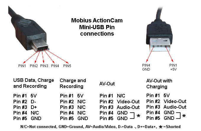
Simultaneous Charging and Recording using standard USB cables/adapters
The cable can be connected to any USB power source as long as the power source can supply 5 Volts under load. Note: Some USB hubs do not supply enough current. If the USB hub can't supply a nominal voltage under load, the camera will run on the internal battery which will be flat before the battery has a chance to charge!
• When powering from the computer, the recording must be started before connecting the USB.
• When powering from an external USB power source, the cable can be connected at any time, e.g. when the camera is turned off, before starting the recording, during the recording.
►Only use quality chargers capable of supplying 1000mA (1A) and a stable voltage of at least 5V. Low quality chargers may not be able to supply enough current and can lead to premature battery failure or, in the worst case, even destroy the camera.

Using external power it is possible to record about 4.5 hours of continuous video (many clips created automatically) using a 32GB micro SD card or about 8.5 hours using a 64GB micro SDXC card. These are average values using standard

Technical
• When the camera is turned off, the RTC and processor draw about 15μA.
• When the camera is turned on, but in standby mode, the camera consumes about 300mA.
• When the camera is recording, the camera draws between 350mA and 400mA.
• In order to protect the battery, the camera will stop recording and turn off when the voltage falls below approx. 3.5V.

Haku made the following measurements
No battery connected
• Standby mode: 225mA @ 4.97v
• Standby mode with AV-Out enabled: 265mA @ 4.97v
• Recording 1080p: 305mA @ 4.97v
• Recording 1080p with AV-OUT enabled: 330mA @ 4.96v
Battery connected
• Battery being charged from flat, powered off: 186mA @ 4.97v
• Battery being charged from flat, recording 1080p: average 505mA @ 4.95v

Using the camera with only external USB power (internal battery disconnected)
The camera can be used without the external battery connected. Remember that the RTC (Real Time Clock) will be reset every time the external USB power is removed.
• The camera requires an absolute minimum of 4.18V to operate correctly. This value may vary with the type of card used. I would think 4.3V would be a safer figure.

A word of WARNING
External power should be a nominal 5V. Fractionally higher voltages (such as from a fully charged 4 cell NiMH battery pack) can be tolerated without undue stress of the camera components.

External USB battery packs
You cannot use a battery box with only 3 AAA / 3 AA batteries unless it incorporates step-up electronics to output 5V.
3 Batteries can only supply about 3.6V, but the camera requires a minimum of approx. 4.7V constant voltage. It will not charge or record when the voltage falls below approx. 4.3V.

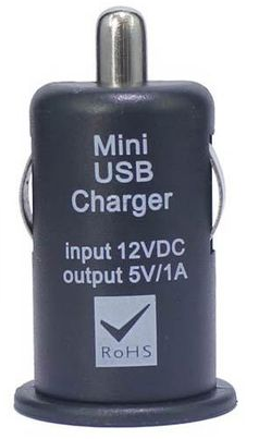
Car Charger (optional)
Any 12V - 15V DC sources which need to be converted to 5V must go thru the car charger electronics (or similar regulator). You must NEVER bypass these electronics or apply 12V directly to the camera - doing so will destroy the camera.
CarBatteryCharger.png
 
I'm still having issues with my unit turning itself off.
This seems to happen only in JPG mode, not video, and only when on internal power.
If I am in JPG mode, and stop taking jpg's by pushing the top button; the camera turns itself off a few seconds later.
If I resume taking jpg's before power off happens , it does not then turn off until I stop photographing.

And if if I am recording on USB power but it goes off; the camera shuts down.

Here's my config, trimmed to eliminate video parameters.
I've read the settings many times and can't see what I've set wrong.
Suggestions?


Code:
Photo Mode Capture Size=[0];set photo size,0:2304x1536,1:1920x1080,2:1280x720
Set Time Lapse Shooting=[3],0:off,1:0.25s,2:0.5s,3:1s,4:2s,5:5s,6:10s,7:30s,8:60s
Photo Flip=[0];set Photo rotate,0:off,1:flip on
....
Power on=[0];set system  power on time,0:delay,1:fast
Power off=[0];set system auto power off time when system pending,0:off,1:30 seconds,2:1 minutes,3:2 minutes,
Auto Record with External Power=[0];set connect with power to start video recording automatically,0:off,1:on,
One Power Button to Auto Record=[0];set press power key to start video recording automatically,0:off,1:on,
Auto Off with External Power disconnected=[2],0:Immediately,1:delay 10s;2:record to low battery power off,
LED=[1];set LED flicker when recording,0:off,1:on,
Charge from USB Host=[0]; when connecting with USB host, charge camera or not,0:on,1:off
Lens option =[0];select lens,0:lens A,1:lens B
Light frequency =[1];set light source frequency,0:50 HZ,1:60 HZ

TV out=[0];set Tv out,0:NTSC,1:PAL,
TV Display Ratio=[0];set display ratio,0:4*3,1:16*9

Motion Detect=[0];set motion detect,0:off,1:on
Motion Detect Timeout=[2];set motion detect timeout,0:5s,1:15s,2:30s,3:60s
Motion Detect Sensitivity=[1];set motion detect Sensitivity,0:high,1:nomal,2:low

.
{TLCAM MOV:TLCAM Mobius ActionCam 2013/12/25 v1.13}
{LDTLCAM,v003}
 
New Firmware v1.17 announced by Tom Frank today at http://www.rcgroups.com/forums/showpost.php?p=27524800&postcount=7166 ...

'This is an interim release which greatly improves the camera compatibility with memory cards! Limited user beta testing has been 100% successful in fixing card compatibility, so hopefully this is a fix for everyone. Please don't populate this thread with "It works!" posts!
wink.gif
If you still have an issue, PM me with details.

There is also a second Wide Dynamic Range setting included that is still in beta testing phase. In my limited beta testing, I could not see any noticeable difference, but maybe in some situations (e.g. night car recorder use?) it's better? If you find any improvements, post some sample images if you can".
 
So maybe for those who are problem free, you should wait till it's out of Beta. Improvements are coming and I'm sure Step 3 Firmware is next. Nice to see they listen to problems and answer quickly. Thanks @russ331 for sharing
 
Having updated from v0.53 to v1.13 last week, I'm disappointed with the night time video quality from v1.13 which, subjectively, seems less clear than I obtained with v0.53.

I had decided to try v0.59 this week, however, I'll give v1.17 a go instead... maybe the second WDR setting will match / exceed v0.53 in low-light?
This http://www.rcgroups.com/forums/showpost.php?p=27370206&postcount=6677 seems to explain the changes a bit. Is motion blur better than noise for dash cam use? Do both user groups share the same goals for low light video?
 
Hi, I just joined and looking to see if the mobius is right for my situation. Does the unit continue to record to the flash card when the AV Out is enabled through pin 4?
 
Hi, I just joined and looking to see if the mobius is right for my situation. Does the unit continue to record to the flash card when the AV Out is enabled through pin 4?
Yes. The only time AV-Out doesn't work is when you connect the camera to your computer - because both modes use the same pins!
AV-Out works when the camera is recording or is in standby or is in playback mode.
 
Night time Video of v1.13 (WDR on) vs v1.17 (WDR off) vs v1.17 (WDR on) vs v1.17 (WDR Low Light on)...


Looks like the 'WDR Low Light' setting may be beneficial for dashcam use.
 
Good news for Android users from therau2000. Live view from Android devices!

* * * Android Update * * *
Great news ! ! !
After spending countless hours searching for a solution
to get the Mobius WebCam mode work with Android

I am proud to announce that I have found the solution :):):) .
I zapped my newly found solution into Mobius firmware v1.17
and
Mobius WebCam mode now works with Android.
I sent the solution to Elijah, the firmware developer,
to incorporate into an upcoming firmware update.
I will therefore release app ExtCam Mobius AC HD soon ;) .
 
Congratulations and thanks for all the hard work!
Now I'll need to figure out if I can use it with my phone or tablet...
 
I've decided to roll back the Firmware from v1.13 to v0.59, having jumped from v0.53 to v1.13, & now disappointed by low-light video quality in v1.13. I think that v0.59 is the best FW available for dashcam purposes at the moment.

I downloaded v0.59 from http://members.ziggo.nl/mobius/ & renamed the zip Mobius FW v0.59

I launched mSetup, but it sees only v1.13. I suspect I'm missing something obvious. What am I doing wrong?
 
I've decided to roll back the Firmware from v1.13 to v0.59, having jumped from v0.53 to v1.13, & now disappointed by low-light video quality in v1.13. ... I suspect I'm missing something obvious. What am I doing wrong?
Not trying v1.17 is what you are doing wrong.
 
Back
Top