Gibson99
Well-Known Member
- Joined
- Jun 20, 2014
- Messages
- 9,293
- Reaction score
- 8,079
- Location
- Houston, we've had a problem, Texas
- Country
- United States
- Dash Cam
- Yes
So I decided it was time to put my Git1 under the knife (or allen wrench, as it were). Tools required were a 1.5mm Allen/hex key, a #00 phillips screwdriver, and a sharp plastic spudger.
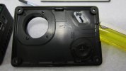
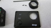
There are 4x 1.5mm allen screws holding the front panel on, and a snap at the center of each long side of the front panel. Once it's off, there are 2 phillips screws holding the lens trim on, so maybe if you were feeling creative or something, you could paint the lens trim a different color than the case. One funny little detail i noticed - the LEDs are mounted at a diagonal to match the openings in the front of the case. they didn't HAVE to do that, but they did. so maybe the board designers had a little fun with it. another thing they didn't have to do was add a piece of foam around the LEDs to prevent light leaks. to me, this shows they actually cared what they were doing and are more interested in making a polished product than just cutting corners wherever possible to save $0.000001 on each unit.
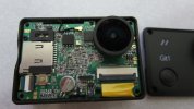
Once the front panel is off, you only have to disconnect the small black wifi antenna lead next to the lens and bend it up out of the way, then push on the screen at the back to push the entire assembly out of the camera shell. the USB and micro-hdmi ports will hang in the case, so it will come out at an angle, SD-card slot first. Look closely and you can see the black wifi antenna glued to the top inside of the shell. You can also plainly see the small button cell battery at the bottom of the front PCB. This is for storing settings and the time/date, so that when you remove the main battery, you won't have to reset everything. This is nice - the last action camera I reviewed didn't have one. it lost its settings every time i removed the battery, which got old fast.
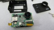
Unfortunately, even once you remove the 3 black phillips screws securing the front PCB and disconnect the 2 ribbon cables visible at front, that's about as far as you can take it apart. there's another ribbon cable for the display, but you can't get to it because of how the screen is attached. you'd have to drill/cut off 4 plastic tabs that were melted in place to secure the screen to the internal frame of the camera. This "melting" style of attaching the screen is more robust than adhesive which might come loose over time and repeated hot/cold cycles, and it won't come loose like screws could. Unfortunately it hampers serviceability. But I'm not an iFixIt reviewer either, so i won't give it a low iFixIt score just because of this. I also thought it was a little weird how the top ribbon cable actually sits partially across the top of the shutter button. looking at the plastic part of the button in the main shell and the button itself, it doesn't look like it'll be an issue since the ribbon cable doesn't move and the plastic button in the shell has a raised + on it which won't contact the ribbon, but it's very tight tolerances, that's for sure!
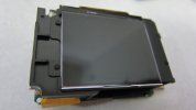
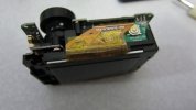
This is about as far apart as the two boards will stretch without disconnecting the display ribbon cable. hard to see in this pic, but the CPU's chip has a big white sticker on it so you can't tell what it is. but it does appear to be a novatek based on everything else i've seen from the software side and what @gitup has said here on the forums. they don't list the CPU on their website; only the image sensor.
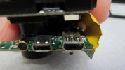
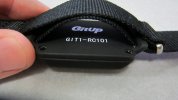
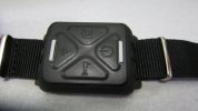
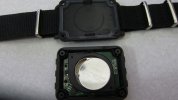
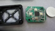
Here you can see the wifi button and its PCB, which contains the antenna for the RF remote - that's the zig-zag trace at the lower left of the PCB. the wifi button is used for more than just wifi - it's the menu/settings button, and can also be used for quickly toggling certain settings. The wifi chipset used is the Realtek 8189ES, which is a B/G/N single stream chip capable of 54MB/sec in G and 150MB/sec in N mode. So the wifi chip should not be the bottleneck if there are any data transfer speed issues.
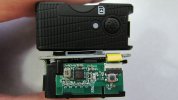
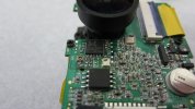
There only appeared to be one dab of glue holding the lens from rotating, so if you ever needed to refocus it, it shouldn't be a big deal. there is no set screw or jam nut on this lens assy.
Overall this seems to be a solidly built little camera.
There are 4x 1.5mm allen screws holding the front panel on, and a snap at the center of each long side of the front panel. Once it's off, there are 2 phillips screws holding the lens trim on, so maybe if you were feeling creative or something, you could paint the lens trim a different color than the case. One funny little detail i noticed - the LEDs are mounted at a diagonal to match the openings in the front of the case. they didn't HAVE to do that, but they did. so maybe the board designers had a little fun with it. another thing they didn't have to do was add a piece of foam around the LEDs to prevent light leaks. to me, this shows they actually cared what they were doing and are more interested in making a polished product than just cutting corners wherever possible to save $0.000001 on each unit.


Once the front panel is off, you only have to disconnect the small black wifi antenna lead next to the lens and bend it up out of the way, then push on the screen at the back to push the entire assembly out of the camera shell. the USB and micro-hdmi ports will hang in the case, so it will come out at an angle, SD-card slot first. Look closely and you can see the black wifi antenna glued to the top inside of the shell. You can also plainly see the small button cell battery at the bottom of the front PCB. This is for storing settings and the time/date, so that when you remove the main battery, you won't have to reset everything. This is nice - the last action camera I reviewed didn't have one. it lost its settings every time i removed the battery, which got old fast.

Unfortunately, even once you remove the 3 black phillips screws securing the front PCB and disconnect the 2 ribbon cables visible at front, that's about as far as you can take it apart. there's another ribbon cable for the display, but you can't get to it because of how the screen is attached. you'd have to drill/cut off 4 plastic tabs that were melted in place to secure the screen to the internal frame of the camera. This "melting" style of attaching the screen is more robust than adhesive which might come loose over time and repeated hot/cold cycles, and it won't come loose like screws could. Unfortunately it hampers serviceability. But I'm not an iFixIt reviewer either, so i won't give it a low iFixIt score just because of this.


This is about as far apart as the two boards will stretch without disconnecting the display ribbon cable. hard to see in this pic, but the CPU's chip has a big white sticker on it so you can't tell what it is. but it does appear to be a novatek based on everything else i've seen from the software side and what @gitup has said here on the forums. they don't list the CPU on their website; only the image sensor.

Here you can see the wifi button and its PCB, which contains the antenna for the RF remote - that's the zig-zag trace at the lower left of the PCB. the wifi button is used for more than just wifi - it's the menu/settings button, and can also be used for quickly toggling certain settings. The wifi chipset used is the Realtek 8189ES, which is a B/G/N single stream chip capable of 54MB/sec in G and 150MB/sec in N mode. So the wifi chip should not be the bottleneck if there are any data transfer speed issues.


There only appeared to be one dab of glue holding the lens from rotating, so if you ever needed to refocus it, it shouldn't be a big deal. there is no set screw or jam nut on this lens assy.
Overall this seems to be a solidly built little camera.
Last edited:

