Power supply

Fletch

New Member
Joined
Mar 2, 2014
Messages
7
Reaction score
0
Country
United Kingdom
Hi all,
I've been making a power supply to be fitted inside my van dash.
The regulator chip I'm using (7805) gets very hot even with a heatsink on it. It's rated at 1.5a max and I'm testing it at 0.5a
Does anybody know what the current draw is during general use on the camera? I think I might need a bigger heatsink if it takes high current continuously.

Thanks, fletch
 
I've put a big heatsink on and it's just Luke warm running at 0.5a. Hopefully it will power the tomtom as well.

The heatsink needed is about 3" square with fins on both sides if anybody is interested.
 
I finished it today and the camera runs at between 370ma and 430ma it kind of pulses between the two at the speed of the LED flash. When on standby it's steady at 300ma.
So not bad at all really, my 7" Google tablet charges at 725ma
 
The problem with the linear 7805 chip is its efficiency. It regulates to 5V, but the "excess voltage" is dropped across the device, at the working current. So if you have a current of 0.5A and a running voltage of 14V, the device is dropping 9V at 0.5A which is 4.5W - significant heatsink territory, and very inefficient.

Get yourself a switching regulator like this which is way over 90% efficient and doesn't get hot. I run my Mini 0801 off one with great results.
 
Yes I've been reading about switched ones but the chips were about £7 each so I decided to finish my linear one.
Thanks for the link though that one looks good.
 
I've just realised the amperage I measured above is total for the camera plus the inefficient regulator so the camera will probably take less than half that
 
Yes I've been reading about switched ones but the chips were about £7 each so I decided to finish my linear one.
Thanks for the link though that one looks good.

You can find quite cheap step down converter circuits on dx eg one picked at random for <£2 :- http://dx.com/p/dc-4-40v-to-dc-1-5-35v-voltage-step-down-transformer-126108#.Uxd6weHftfl (I'd be inclined to buy a cased one for a car)

Note the quoted max current will usually be the max with a larger heat sync fitted, not the circuit as supplied. I guess it might be worth adding some over voltage protection - http://axotron.se/index_en.php?page=26
 
Last edited:
I've just realised the amperage I measured above is total for the camera plus the inefficient regulator so the camera will probably take less than half that

You misunderstand how current (please not "amperage"!) works, then. The current you measure flows through the entire circuit as the regulator and the camera are in series.

The voltage is split: you put a nominal 12V across your regulator/camera "chain", the regulator ensures the camera gets 5V by dropping 7V itself.

As a result, the power dissipation is split: total is 12V×0.5A=6W (varies with input voltage); regulator dissipates 7V×0.5A=3.5W (varies with input voltage); camera dissipates 5V×0.5A=2.5W (constant due to the regulator).
 
I understand current & voltage well, I just forgot i had put the multimeter in series with the power supply as I had already soldered in the USB socket.

Current does sound better yes, amperage is a word though, I looked it up..
PS is potential difference better than voltage?
 
I understand current & voltage well, I just forgot i had put the multimeter in series with the power supply as I had already soldered in the USB socket.

The problem was your statement "the amperage I measured above is total for the camera plus the inefficient regulator so the camera will probably take less than half that".

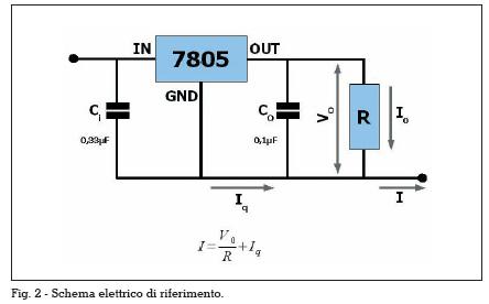
7805_schema_elettrico.jpg


I guess you're measuring the current between vehicle 12V and 7805 pin 1, call it 502mA. This is I in the diagram. That current will be split between the regulator operating current (to ground through pin 2, shown as Iq) and the load itself (to ground through pin 3 then the camera (R), and is shown as Io).

The regulator draws very little current to do its job - if you measure the current between 7805 pin 2 and ground, it'll be about 2mA depending on the 7805 chip itself. This is Iq in the diagram above.

The remainder (500mA) goes out of pin 3 and through the camera, Io in the diagram. The voltage at pin 3 is 5V, so the internals of the 7805 need to "absorb" the other 7V whilst passing 500mA.

The point is that the camera draws pretty much all of the measured current. The 7805's inefficiency isn't from its regulation control circuitry, it's from the way it "gets rid of" the excess voltage.

I would have built a switching regulator, except I found (as you have) that I can't get close to the price of a pre-assembled one. I really can't fault mine: small, well-packaged, runs cold, capable (5V 3A from alleged input of 8-23V) and cheaper than I could get the IC on its own.
 
Yes I see, its the same why you can't use LEDs off high voltages, the resistor gets too hot.

I got on the wrong track with it because I tested my Google tablet on a little car USB adapter and it only took about 200ma (it took 725 on my linear charger with data pins shorted) but the data connections on the car USB adaptor must be 'telling' it to take less.
 
Back
Top