Nextbase 212 Hardwired - Not switching on

utojcartwright

New Member
Joined
Feb 7, 2022
Messages
3
Reaction score
0
Location
england
Country
United Kingdom
Hey there,

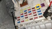
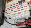
I've got a Suzuki Swift SZ4 2015 and a Nextbase 212 (NBDYR212-R28). Only recently decided to install it and I've gone for the hardwired option. I wasn't sure which fuse to utilise so I did some googling and found that the ACC2 fuse is best. The problem is after using that and grounding the device it does not switch on when I start the car. It works when I run it off a USB via plug socket. As the fuse I took out is a low-profile mini, I wasn't able to put it in the piggyback portion of the Nextbase adapter, not sure if that's an issue or not.

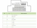
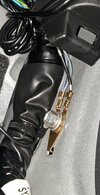
I've attached a screenshot of the fuse diagram, I used number 9, and one of the ground too. I've not really done any electric work before so I wasn't sure if the ground was fine.

Any help would be appreciated,

Cheers
 

Attachments

  • ACC2.JPG
    ACC2.JPG
    78.3 KB · Views: 5
  • ground.JPG
    ground.JPG
    43.2 KB · Views: 5
Can you attach a picture of what you have done with the fuse, I suspect your issue lies there.
 
Sorry for the late reply;

The circled fuse is the one that has been removed and as it's a low profile type it won't fit in the adaptor to piggyback. I wonder if the fuse attached to the Nextbase fuse adaptor is dead?
 

Attachments

  • dashcam2.jpg
    dashcam2.jpg
    249.8 KB · Views: 6
  • dashcam1.jpg
    dashcam1.jpg
    497.2 KB · Views: 6
Sorry for the late reply;

The circled fuse is the one that has been removed and as it's a low profile type it won't fit in the adaptor to piggyback. I wonder if the fuse attached to the Nextbase fuse adaptor is dead?
It’s possible that the voltage is on the right leg of the fuse as you look at it on the picture, that would mean you would need to have a fuse in the other slot of the fuse tap as well or turn it around. I suspect in your case you don’t have clearance to turn the tap around because of that raised section of the fuse box. A voltmeter or multimeter would be able to confirm which side has the voltage.
 
Be aware there is a right and wrong way to connect a piggy back fuse. When you look into a fuse box, one end of fuses is connected to the 'bus-bar' ( which is the main conductor supplying power to fusebox ) and the other end of fuse feeds out to the equipment it is supplying and protecting - but actually the fuse is there to protect the wiring from overheating ).
Looking at a piggy-back holder there is an end with no cable this is the 'common' end of fuse holder, the other end has a cable coming out to feed whatever you are connecting. The piggy-back should be connected so the end without cable ( common end ) goes to 'bus-bar' end of fuse socket, otherwise the two fuses will be in 'series' when they should be in parallel.
Why does this matter, well, in series the current is flowing through to original fuse first and then through the piggy back, so the original fuse is seeing the current to the original device plus the current being tapped off to your new device(s), this could overload original fuse.
Easy way to find common end is that with original fuse removed it should still have power on the busbar end when you poke voltmeter prod in there ( providing ignition turned on ).
 
Back
Top