SPL15
Member
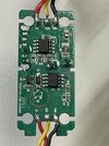
Pretty simple: Remove Q3 from PCB to disable the automatic low-battery cutoff if you’re wanting to be able to discharge dashcam batteries to 0%.
DO NOT PERFORM THIS MOD IF YOU ARE RUNNING OFF LEAD ACID BATTERIES, OR YOUR CAR’S STARTING BATTERY. Do not do this mod unless you know exactly what this mod is going to do to your batteries without having to ask someone else what it will do to your batteries. If you perform this mod w/ your car’s battery as the power source, you will more than likely irreversibly damage the battery due to way over-discharging it, and could possibly damage expensive electronic control modules in your vehicle.
Disclaimer: Perform at your own risk. I’m just a random stranger on the internet, I could be full of BS and stupid like most random strangers on the internet are.
Notes / Observations:
With Q3 removed, the buck-regulator inside the HK3-C power module will regulate down to around 7 VDC from the battery pack(s). Operation below 10 volts or so is unknown, & could potentially cause issues w/ component heating / unreliability due to the higher peak current pulses required for a given power output. It’s likely OK to run low voltage, but I would try to stay around 10.5 - 11 VDC minimum to be on the safe side with a 3-ch setup. If there are issues running low voltage, increasing inductor size & value would most likely get things working reliably & more cool.
Transistor Q3 is what switches the NDP1335KC PMIC into standby mode on pin 7 (FS). Without Q3, the step down converter PMIC never receives the “low-battery voltage” standby signal from the ChipSea CSU32P10 MCU.
The voltage selection switch effectively has no effect w/ Q3 removed; the MCU still monitors +12bat & fires the standby signal when low, but there’s no Q3 to pull down Pin 7 on the PMIC to put it into standby mode. I removed the voltage level switch & jumpered it, but this isn’t necessary (I only removed it because I don’t want the lever sticking out of the housing).
MCU logic for the ACC input & output signal remains the same; there is no difference in operation w/ Q3 removed.
Because there’s no shutdown signal with Q3 removed, the dashcam will receive power & be put into parking mode whenever 7 volts or more are applied to the HK3-C’s +12VBat input. ACC output to dashcam works fine down to 7 volts input as well.
The PMIC is rated 7 - 32 VDC input, up to 3A output. Output voltage is set via resistor network, there’s also the ability to add output voltage resistive loss compensation (I might play w/ this later on). There’s reverse input voltage protection via series diodes on the +12vbat & ACC inputs.
Current limit of 2.0 amps stated by Viofo is likely due to size of the buck-regulator inductor (both value wise, wire gauge, & core saturation), as well as input & output filter cap values. Could easily increase max current output to the 3 amp limit of the PMIC by increasing inductor value, gauge, & core size, as well as input & output cap values (need to be low ESR caps w/ high ripple current rating).
The low voltage cut-off is set via a resistor network w/ a 5 VDC reference that’s also the MCU’s 5 volt power source (MCU is powered directly off the +12bat input via a basic 3-pin linear regulator). The voltage level switch connects ADC 0 input to different voltage potentials on the resistor divider network, the resulting voltage to the MCU is used to compare against the +12bat voltage that’s also divided thru a resistor network. It’s not easily feasible to change the low-bat cutoff voltage to be below 11.8Vdc due to the logic being internal to the MCU & the lowest setting of 11.8vdc being referenced to 5Vdc (which is the highest voltage available). Could potentially play w/ the +12Bat resistor network to fool the MCU.
Attachments
Last edited: