Viofo to cellink neo+8

Jackbauer78

New Member
Joined
Mar 26, 2023
Messages
7
Reaction score
0
Location
Sussex
Country
United Kingdom
Hi therei have celllink neo+8 , do you need the parking mode voltage box thing, i cut my viofo lead so the voltage monitor box so the lead no longer used the voltage monitor box , i just wanted to lead with the usb connection on the end to connect to the camera so i cut it and joined it to the cellink neo lead that is the output for camera power , my camera won’t turn on now is this because I deleted the viofo hard wire box, my thought was that voltage monitor box was not needed when the cellink neo battery was used.
any help much appreciated, picture is from someone elese set up , mine same just i cut the voltage box of as thought not needed AFEADEA5-4A42-47B3-B65F-5C9989A6BB96.jpeg
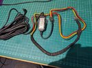
 
The "voltage box thing" is more than a low voltage cutoff device. It converts the 12-volt input power to 5-volt power that is supplied to the dash camera via the USB connector. You cannot directly connect the battery pack's "dash camera" output power (12-volt power) to the USB power wires that go the USB connector for the camera.
 
Last edited:
Does the camera power on with the 12v lighter socket power supply or have you toasted the unit?
I know of someone who fitted a road angel years ago and just chopped the 12v plug off and wired it straight in. Killed the road angel.
 
The "voltage box thing" is more than a low voltage cutoff device. It converts the 12-volt input power to 5-volt power that is supplied to the dash camera via the USB connector. You cannot directly connect the battery pack's "dash camera" output power (12-volt power) to the USB power wires that go the USB connector for the camera.
Oh ok that explains why thanks for that I assumed the cellnet neo does that conversion already As its intended for dash cams , was hoping to not use the viofo hardwire box as there unreliable last about a year and stop working have replaced them a few times now.
my viofo has chunky wire on the on the 12volt input side and thin for the 5volt output side of the hardwire box but notice the cellink neo has thinner 12volt output wires ,is it ok to use the suppled cellink output wire and join it to the thicker wire viofo wire as its all drawing 12volt anyway to the output of the viofo box .
hope I’ve explained it well, thanks for the help
 
Does the camera power on with the 12v lighter socket power supply or have you toasted the unit?
I know of someone who fitted a road angel years ago and just chopped the 12v plug off and wired it straight in. Killed the road angel.i tried it out to see if it works thanks goodness
i just tried the 12volt lighter socket wire out and all good thank goodness
 
my viofo has chunky wire on the on the 12volt input side and thin for the 5volt output side of the hardwire box but notice the cellink neo has thinner 12volt output wires ,is it ok to use the suppled cellink output wire and join it to the thicker wire viofo wire as its all drawing 12volt anyway to the output of the viofo box .
The Cellink Neo 8 likely provides an output wire harness with 24 AWG wires. I'm not a fan of that gauge wire being used, but it should work. I've created my own wiring cables to plug into the that style connector that can have 20 AWG wire (at max).
 
The Cellink Neo 8 likely provides an output wire harness with 24 AWG wires. I'm not a fan of that gauge wire being used, but it should work. I've created my own wiring cables to plug into the that style connector that can have 20 AWG wire (at max).
Thanks for the replay
i was thinking the same seems thin which is why I thought it was ok to wire the way i did as it matched the wire size on the viofo output side of the box.
i really didn’t know i would need that vifo box as thout the camera itself converted the 12volt to 5volts internally in the camera,
not a fan of the viofo hardwire box as they last about a year i find then stop working but if its needed and no alternative it will have to do
In general, when the dash camera receives its power via any type of USB connector, there's some sort of external to the dash camera device converting the vehicle's 12-volt or 24-volt DC power into 5-volt DC power. If the dash camera uses a small barrel type power connector, it uses the vehicle's 12-volt power (or 24-volt power if the dash camera is compatible with that voltage level) to power the dash camera. Examples of dash cameras with barrel type power connectors are BlackVue, Thinkware, FineVu. If the dash camera accepts the vehicle's power directly (without conversion), then the dash camera itself usually will have some sort of low voltage cutoff functionality directly in the dash camera.
 
makes sence now and explains why it needs the viofo box .
I’ve ordered a new hard wire kit now as i cut the wire to short near the box to join it back together, am assuming as the neo has constant 12volt out out it doesn’t make any difference what voltage cut of you set on the viofo hardwire box.
do you think its needed to add two inline fuses to the red and black outout wire on the hardwire kit as it was before originally when taking power from the fuse board
The output voltage from the Cellink Neo is not a constant voltage value. It will be higher when the battery pack has a full charge and it decreases as the charge level of the battery pack decreases. I would set the VIOFO low voltage cutoff setting to the lowest value of 11.8 volts when connected to a dash camera battery pack.

It certainly wouldn't hurt to put an inline fuse in the yellow and red wires going to the VIOFO hardwire kit.
Thanks for the help you been of great help, i will finish it of hopefully at the weekend,only got to splice the hard kits now into the neo output wire then put everything back together .
 
Good info! I’m currently in the same situation with my SGDC2K. This thread explained a lot. Hopefully I didn’t fry my cam with 12v straight from cellink.
Would a voltage step-down module work intstead of original low voltage cut off box? The reason I am asking this is because with original low voltage cut off the camera would stop recording at 11.8v and that would be not utilizing the entire cellink capacity and resulting in shorter parking mode run time, I think when 4s lifepo4 is at 0% it should be 10v. I appreciate any input. Thank you and happy dashcaming everyone!
The lowest voltage an EGEN produced LiFEPO4 battery pack will output is 11.0 volts (in my testing). Yes, any hardwire kit with a low voltage cutoff feature will leave some amount of the battery pack's charge left unused for parking mode. We're trying to convince VIOFO to either add a much lower setting for the low voltage cutoff feature or add an "off" setting. You might be able to get the dash camera to power up with a voltage step down module, but you won't have parking mode working since it won't trigger the acc on/off logic in the dash camera. That's much the same as powering the dash camera directly from the USB port on the battery pack. The best/safest approach to power the dash camera is to use the manufacturer's hardwire kit (for now).
 
Thank you for the answer! I understand that using manufacture’s supplied kit is the safest way. I’m not trying to reinvent the bicycle here, I just like to ask knowledgeable people a lot of questions, for my own education . So the question is, would it be incorrect to use two of the voltage step down boxes, one for ACC and the second one for B+, grounded to the same grounding pin of the battery? So this way we get 5v on both wires and let the battery control its low voltage cut off.
Thanks!
 
A step down module would give you 5 volts which would need to be fed into the USB cable wires. You would have to cut the USB cable going to the dash camera and splice in the ground, 5V BATT+ and 5V ACC+. That sounds like reinventing the wheel to me. Others with more USB cable knowledge may add to this discussion.
 
Back
Top