Parking Battery-Power Station, 3X capacity and 3X cheaper than dedicated options + extra functionality

There are several settings in the menu that will enable parking mode. One is for "enabling" parking mode and this mode is likely impacted by what the camera "sees." The more static the image that it sees, the more likely it is to enter parking mode. There is a sensitivity mode for this, set it to "low." Having said that, sometimes mine will switch into parking mode while the engine is running and I'm sitting still (waiting to pick up a kid in the evening) and sometimes it doesn't - it seems to be a little variable. Perhaps this is a function of the level of activity that the camera sees while siting still.
 
Then you're outta luck, it worked for me a bit but then I hardwired it.
 
So my camera completely lost power when i was driving today, couldn't understand why. Did the dc-dc booster die? Did the Ecoflow run out of juice?
No my backpack that was in the trunk must have knocked the cable out of the USB port when i slammed on the brakes :LOL:
Now I put the velcro straps on top of the cable.

20240306_163405.jpg
 
Among the range of things that can go wrong, that one is the easiest to address ;)
 
Finally got my usbc power tester, I set the voltage to 5.66v near the Ecoflow and got 5.33v at the dashcam. The wiring is around 2 feet longer than the hardwiring kit without the voltage converter.

20240408_185232.jpg
 
Now that it's been a little while, did the voltage booster cure your intermittent reboots? Mine's been running fine since I ditched the relay idea.
 
Finally got my usbc power tester, I set the voltage to 5.66v near the Ecoflow and got 5.33v at the dashcam. The wiring is around 2 feet longer than the hardwiring kit without the voltage converter.
I use this calculator for LTO battery, easy to estimate voltage drop for different AWG wires and length


Attachments

  • Voltage drop calculator.JPG
    Voltage drop calculator.JPG
    86.4 KB · Views: 9
I posted couple of videos on LTO battery thread, where I use "UPS" or "Dual Power Transfer Switch" to de-couple power for DVR from power components inside the battery.

The first UPS (the red one used for LTO battery) is not adjustable and is for 12V system only, I tested it separately with power station and Viofo A229 Plus, and it works! Flawless switching.
Then I tested the second, black adjustable UPS, per spec operating voltage range is 6V-12V, however I was able to adjust it for 5V.
Unfortunately, with 5V setting, it works fine for Mini 2 but not switching fast enough for A229 Plus, unlike 12V setting which works as good with A229 Plus as the red one.

I am thinking may be to switch my 5V system into 12V, it is easy with my power station not having ON/OFF switch for 12VDC output.

For Ecoflow River 2, I guess, that voltage booster can be replaced with 5V to 12V booster in order to implement UPS if desired, unless it is possible to get inside and make 12VDC switch permanently ON, when station is turned ON.

 
Last edited:
That's the same wire gauge calculator that I found a little while ago. I was also thinking that the 12v wiring setup retaining the Viofo voltage step-down regulator might be somewhat less sensitive to intermittent voltage drops during switch over than the camera is while running of 5v without the regulator box.
 
That's the same wire gauge calculator that I found a little while ago. I was also thinking that the 12v wiring setup retaining the Viofo voltage step-down regulator might be somewhat less sensitive to intermittent voltage drops during switch over than the camera is while running of 5v without the regulator box.
I also thought that perhaps the HK4 voltage step down regulator acts as a buffer to help with momentary voltage dips.
With LTO battery, I do not use HK4 Voltage step down regulator, instead I use pair of non-brand 12V to 5V step down converters and the UPS, works fine with A229 Plus.
It could be that Converters are helping, perhaps like HK4, or the UPS is simply switching faster at 12V.
 
As an update for my setup with the NECESPOW 322Wh and a solar panel. I mounted the solar panel like I described a previous post (here). I currently have the solar output going directly into the power station DC input, and a fuse tap charging via USB-C when the truck is running. The USB-C seems to generally be charging at ~50W (the adaptor should be able to do 65W, but I don't seem to see that with my setup). I have my dashcam to do parking recording based on events and motion, and its probably over-sensitive. My drive to work is usually about 1hr15min total (out+back). Using only the USB-C charging while driving, the power station would run down after 1-1.5 weeks, then need to be taken inside to recharge. Since hooking up the solar, it seems to stay pretty much fully charged, but the display on the NECESPOW doesn't give you much reliable info on the actual charge state. I can only really tell that it is fully charged when it exits charging mode with power connected (battery indicator not blinking). I purchased a digital meter to monitor the amount of solar power I am getting (this one, but there are lots identical on Amazon). I have it wired with these barrel connectors, and have any easy point under my bed cover to plug in the meter. While parked at work on a sunny day, from 8am until 4pm, I get around 85-90Wh. That works out to a little over 10W on average over that 8 hours. The sun is pretty low on the horizon at 8am though, so some of the time the output is probably pretty low. Full noon sun seems to get about 15-17W (the panel is sold as 20W). Overall, it is working out pretty well. Here is what the setup looks like:
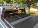
solar.jpg

I mounted it using some aluminum angle, and used a just the gland nut off of one of these from Amazon. The panel has a little air space below it, and I can still fold the cover back without anything touching the panel.

Here are a few of my thoughts:

- The power gauge on the NECESPOW power station is very unreliable. It very difficult to know exactly what level of charge it is at (unless it out or completely full).
- The solar panel does poorly on cloudy days, but has enough to keep the power station in "charging" mode (battery status flashing). I am wondering if it burns more battery staying in "charging" mode when the solar input is very low, but I can't tell for sure (see statement above).
- I like having the power meter, but I can currently connect it in the bed of the truck, but I don't want to leave it there while driving. I may adjust the wiring so that I can keep the meter inside the truck. I also may get another to measure how much the dashcam is actually using (to play with parking recording settings).
- The NECESPOW has a 12 hour timer, so it sometimes shuts off parking if I haven't driven in more than 12 hours. I was hoping that the solar panel would keep it on (the solar charging keeping the 12 hour shutdown reset). I still have it stop parking recording overnight some times, so either we have 12 hours without enough sun to put the power station in charging mode, or something else it going on.

Overall, its all working very well. The dashcam works flawlessly (back and forth between driving mode and parking mode). Except for extended cloudy days, it keeps the power station pretty close to full I think.
 
Thanks for the update, @kawayanan
Your installation is one of the rare cases of successful solar panel implementation.
It looks very clean and nice. Many have tried and failed.

Yes unfortunately PS display is almost useless. This is not specific to Necesspow only.
My Bluetty EB3A is similar. I am not sure about Ecoflow, may be @EricSan and @forcefed can provide some insight.
The problem is that all these devises are designed to operate with much higher Current and are calibrated accordingly.
They simply are no accurate with milliamps, and since they calculate state of the charge (SoC) based on Ah we get what we get.
I have the same problem with 3 different smart BMS for LTO battery project. I can accurately calibrated for 10A charging or 300 mAh for dashcam draw, but never for both at the same time.
This power meter has a low voltage limit 6.5V hence will not work to monitor dashcam power draw if you are running 5V system.

10W per hour average from solar panel is very good. 80Wh is good for about 15h parking in predictable low bit rate mode for 2CH.
I would still install anti-back-flow diode, the "Ideal Diode" is very efficient with minimal voltage drop like this one:
https://www.amazon.com/gp/B0BM4QMJ9V
In my tests with 2 different solar panels and different PSs there was about -1W back-flow in shade.

50W from USB-C is low, should be between 60-65W.
In my experience it could be due to multiple grounds, generating some difficult to understand current flows.

Tomorrow I will test my N-300 to see what is my charging rate.
 
Last edited:
I picked up a USB voltmeter a few weeks ago (https://www.amazon.com/gp/B09T3KHBFL) so I'm able to compare the EcoFlow display with the external voltmeter. I find them to track very closely with one another. The EcoFlow display indicates a steady 6w power draw for the dual-camera Viofo A139 Pro and the USB meter shows power draw fluctuating between 5.6 and 6.3w. Similarly, I've found the remaining hours of battery power to be fairly accurate, though my pattern of working changed right when I installed my EcoFlow battery (temporarily working from home more frequently). It seems that the battery capacity is enough to power my dual camera for about 40-45hrs, and this tracks well with the number of hours that the camera has been operating, so it, too, is reasonably accurate.
 
...
This power meter has a low voltage limit 6.5V hence will not work to monitor dashcam power draw if you are running 5V system.

10W per hour average from solar panel is very good. 80Wh is good for about 15h parking in predictable low bit rate mode for 2CH.
I would still install anti-back-flow diode, the "Ideal Diode" is very efficient with minimal voltage drop like this one:
https://www.amazon.com/gp/B0BM4QMJ9V
In my tests with 2 different solar panels and different PSs there was about -1W back-flow in shade.

50W from USB-C is low, should be between 60-65W.
In my experience it could be due to multiple grounds, generating some difficult to understand current flows.

Tomorrow I will test my N-300 to see what is my charging rate.

Since I bought a pack of barrel connectors, I should be able to easily rewire a few points in my setup to use power meter. I left my Viofo hardwire kit intact and am using the 12V output from the N-300 (the standard adaptor in the hardwire kit drops it to the 5V). This means that as long as I use the power meter at the 12V N-300 output (before the hardwire kit), the power meter should be able to work, and would give me the power draw of the camera plus the lose at the 12V to 5V conversion (actual full draw on the power station).

I had actually been looking into anti-backflow, but didn't know exactly what I should be looking for. Thanks for the suggestion. Not having done too much with electronics, I assume the in and out on those boards are designed for the wires to attached via a nut (as opposed to solder connection)? Do you know what hardware is standard for these?

Yes, my USB-C is low, and I am not sure exactly why. I simply haven't looked into it since everything is working reasonable well.

I still thinking about trying to setup with a relay for dual charging from the battery while running and solar when not. I post what I am thinking of before making any stupid mistakes.
 
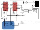
Wired up the Viofo A139 Pro and EcoFlow parking battery in my son’s 2014 Mustang GT today. The Mustang presents an extra challenge over my Volvo install because the 12v utility outlets are always on (don’t go off with ignition). So I needed to add a heavy duty relay in the middle of the 12v charging cable that came with the EcoFlow battery. The relay is controlled by an Add-a-Fuse with a 5A fuse that I installed in the passenger foot well fuse box. I used fuse location #37, which is indicated as an “unused (spare)” slot in the manual, but it had a 10A fuse installed. Not trusting the “unused” indication in the manual, I restored the 10A fuse to its original location and added a 5A fuse for my purposes. The Add-a-Fuse powers his radar detector, the heavy duty relay for EcoFlow charging, and the 12v to 5v Viofo regulator.

I removed the 12v to 5v regulator from the hardwire kit and used it separately as a 5v voltage source for the yellow parking mode trigger wire. Because of the way that the EcoFlow unit works (12v outlets must be manually switched on every time, but USB outlets always power up when the unit receives a 12v charging voltage), I wired the Viofo with a 5v wiring setup. The Viofo 5v regulator and the heavy duty Bosch style 40A relay were installed in a small, black plastic project box to keep everything neat and protected. The project box is strapped down under the passenger seat and the EcoFlow battery pack sits on the floor in the rear passenger foot well. We slid the passenger seat back to hold the battery in place. This worked well because Mustang rear seats are more ornamental than functional ;) . The 12v power supply for charging the EcoFlow plugs into the utility outlet in the center console and we fed the wire out of the bottom of the console which keeps it out of the way. Everything is fused and protected. The high current EcoFlow charging wires are all wrapped in split loom plastic wire protector and zip tied to the stationary frame of the seat so it won't cause any trouble for moving the seat back and forth.

Big thanks again to GPak for starting this thread by sharing his work (y).

Here is the wiring diagram for this install. The red dotted line indicates the contents of the plastic project box:

Dashcam Wiring.jpg

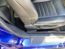
And here is what the actual install looks like on the passenger side of the car. You can see the EcoFlow behind the front seat as well as the black project box between the seat and the door sill. The two black wires are the only “exposed” wires for the whole install and they are well out of the way for passengers getting in and out of front seat.

IMG_4474.jpeg
 
Last edited:
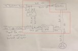
Okay, here is my next attempt at designing a setup to due dual charging from the vehicle while its running (USB-C and 12V), and then switch to solar when it is not. Also trying to isolate the solar completely from everything but the power station (vehicle battery/wiring, and chassis). The vehicle battery is under the back seat, as well as storage space where the power station and wiring could sit, and I would only need a fuse tap to let the dashcam know to move to driving mode and to signal the relays. For the relays I was looking at these 12V DC 8 pin DPDT. I could leave the USB-C charging on the fuse tap and only need one relay, but I think this setup would fix some of the decreased power I was getting with the USB-C (more direct connection to the battery + and - ). That and the relays come in a pack of two :) .

dual charging with solar (DPDT)jpg.jpg

The relay powering the USB-C would be connected to the normally open side of the relay (so it only draws on the vehicle battery when it is running (triggered by the fuse tap). The solar/12V charging relay would have the solar connected to the normally closed (close when the vehicle is off), but switch to charging from the battery when the vehicle is running. I think this should keep the solar completely isolated (direct to the power station via the NC side of the relay when the vehicle is off), and disconnected from anything when the relay is activated.

Do I need to worry about the power from the battery to the 12V input on the power station not being having anything to limit the amperage draw (other than what the power station limits itself to and the 10A fuse)?

Thanks for any comments and suggestions! Let me know if I screwed something up.
 
Back
Top