Parking Battery-Power Station, 3X capacity and 3X cheaper than dedicated options + extra functionality

Alright, I got some stuff to mess around with. :)

As I mentioned, I use this is a pickup with a tri-fold hard bed cover. The way it fold up, there is a space on top of the back third once folded. It has foam bumpers to go between the top of the back section and the folded parts. The space between the foam bumpers is about 15" (I could in theory move them too), and the back section is also about 15" deep. This seemed like a perfect place to put a solar panel. It wouldn't be in the way, the bed cover could still be folded without moving or damaging the panel, and being behind the cab I don't think it should get too much wind when driving. I went looking for a solar panel that seem reasonable, not too expensive, and I wanted the frame to be black to not stick out too much. Wheat I found was this. It was small enough, black frame, and had a 50% coupon making it $27.50. It may not be the best panel, so I'm not recommending it - it just met my criteria.

I decided to change the connection type to MC4 solar connectors, partly to have better connectors, but also to make the connection to the PS easy. There are MC4 to barrel connection plugs available on Amazon and it was easy to find one that would work with the DC input on my PS. This one was $13.59 when I bought it (there are a bunch on Amazon though).

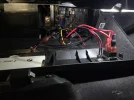
Here is what it looks like when checking it out.
PXL_20231228_221027693.jpg
I tested it out quickly flat on the ground, at ~4:10pm (sun getting low on the horizon). When not connected to a load, the voltage from the panel was 20.0-20.8V (not sure of an easy way to check the voltage when connected to the PS). When connected to the PS, it woke it up as expected and the icons were showing it charging. The PS isn't like the nice ones that give you the power stats in and out, but my multimeter showed ~0.70-0.75 amps. If that's right and the voltage stayed at ~20V, it looks to be putting out 14-15W, which is honestly better than I expected for a cheap 20W panel off Amazon (and not with direct overhead sunlight). I think tomorrow I will try to check it with the sun overhead, and if I put the panel inside my windshield (just curious how much is lost going through the glass).

I'll still need to work out the mounting on my bed cover. The electrical connection on the back of the solar panel sits just proud of the frame, so it cannot be mounted flat. I'll have to get some L-channel to make some mounts and rubber grommets for the bolts and wires to go through the bed cover.

If my explanation above didn't make sense, here are some picture of how it should sit on the hard cover, and how it stays out of the way when it is folded up. I want to put the wire through under the panel.
PXL_20231228_222107844.jpgPXL_20231228_222440652.MP.jpg
 
Okay, I did a little bit of testing. This morning I attached the solar panel to the PS inside my truck at work. I put it inside of the windshield.
PXL_20231229_175914425.jpg
I put this in place a little before 7:30 in the morning, and the sun was only about a quarter over the horizon (so morning light, but no direct sunlight yet). Interestingly, when connected the PS showed charging. If I covered the panel, the blinking charge status stopped (not charging). Its not getting any energy (confirmed with a multimeter), but maybe it is enough to wake up the PS. I left in this way until noon when I was done working for the day, and then did some checks with full sunlight (not a cloud in the sky). Inside the windshield, the multimeter showed 0.25-0.35A, presumably at around 20V. Outside flat on the ground, I got 0.6-0.65A. Being winter, the sun was not directly overhead, but when aimed at the sun (~45 degrees) I saw anywhere from 0.7-0.85A. There did seem to be a lot of viability in the amperage measurement. I don't have much experience using a clamp meter for DC voltage, so I don't know what's normal (nor is my meter high end by any means).

Two thinks I noted:
1) I didn't see much, if any, change in the charge status indicators on the PS after ~4 hours in the sun. I'm assuming that the PS should not backfeed the panel through the DC input (or at least I hope not), but I also don't know if the panel has any blocking diodes built in. For my own peace of mind I think I will want to verify that the PS won't be loosing power back to the panel when there isn't sun out.
2) The panel does very badly when partially shaded I think. If I shade even a small bit of it (1-2% of a corner), the amperage I can read drops drastically. It might be an argument for getting an amorphous panel like most of the flexible/foldable ones are. I think they are supposed to do better when partially shaded.

I would really like to be able to get a better amperage readings and also see the voltage at the same time. I may order something like this power monitor to help me there.
 
You know, dashcams sandwiched between the windshield and one of those sun blocker things,,,,, well lets just say we have seen buttons melt on some cameras.
Other than that pretty darn cool.
 
20V is Panels open circuit voltage, under the load it is likely around 14-18V at best.
Measuring such a small current with clamp meter is hardly trustworthy.
Better to use this
https://www.amazon.com/gp/B07M8T3T2C
with combination of this
https://www.amazon.com/gp/B09Y1DS2B9
Between Solar panel and Power Station.

One thing is for sure: a windshield cuts the solar panels power output in half.

And yes, if the solar panel can charge/wake up the N300, it will reset the 12-hour auto shutdown for continuous parking recording.
 
Thanks to al for all of the great content here! I'm in the process of building a wire harness for a Power Station for my Viofo A139. My question is about the choice of the Power Station: a Necespow or an EcoFlow River 2. The main difference that I'm seeing for my context is the Necespow can operate up to 60C (140F) while the EcoFlow is rated only to 45C (113F). I live in central PA and summer temps will reach 90+F, but I've never measured the temps in the trunk of the car where the power station will be mounted.

Is the EcoFlow not a good choice in this context?
I'd be a bit weary that the Necespow has higher operating temps than the ecoflow, battery tech is similar between the two. Plus the river 2 has a cooling fan in the back, not sure if the Necespow has one.
 
Thanks to al for all of the great content here! I'm in the process of building a wire harness for a Power Station for my Viofo A139. My question is about the choice of the Power Station: a Necespow or an EcoFlow River 2. The main difference that I'm seeing for my context is the Necespow can operate up to 60C (140F) while the EcoFlow is rated only to 45C (113F). I live in central PA and summer temps will reach 90+F, but I've never measured the temps in the trunk of the car where the power station will be mounted.

Is the EcoFlow not a good choice in this context?
I think manufacturers, especially reputable ones like EcoFlow, are being overprotective.
Most of the high temp limitations could be related to Power Stations max rated operations, like high power input/output and/or inverter operation, which is not the case for Dashcam use.
The highest heat in a car is during long parking under the Sun, with no air-conditioning and rolled up windows, but that is when parking power draw is very low and no charging.
The hardest time is right after long parking when ignition is turned ON and PS starts charging.

I did run Necespow through very hot days on summer, here in Savannah GA, with no problems, after long parking, when ignition is turned ON and PS starts to charge, the Necespow internal fan will engage, and it continues to work.

EcoFlow is nicer Power Station and I like having an App, to monitor PS status and adjust certain settings.
I think it should be fine for hot conditions.
 
Last edited:
Thanks for the additional insights. My guess was that the temp differences are mostly related to being more or less conservative with ratings given than the battery chemistry is identical. I like the longer warranty and better reputation of the EcoFlow unit.

GPak, I haven't found a relay that I like yet to isolate the Power Station for charging while the engine is running, but there are plenty of nice, plastic project boxes out there. Here are a few:

Project Boxes
 
I'd be a bit weary that the Necespow has higher operating temps than the ecoflow, battery tech is similar between the two. Plus the river 2 has a cooling fan in the back, not sure if the Necespow has one.

The Necespow does have a cooling fan at the back. So for for me, it has only ever come on for a second right as it starts up. My assumption is that the most internal heat is produced when using it as an inverter (using the AC output), which I am not using it for.

Depending on what you want to use the PS for though, I think there are two main point between the two (though I haven't used the EcoFlow, so its just based on specs):

1) The EcoFlow actually gives you data from its display (charge status, input and output rates/power, etc.). The Necespow just gives you a 5 bar display on its charge status (+/- 20% at best, but for me it has seemed pretty unreliable). I would assume that the EcoFlow app gives you even more info.
2) The Necespow has a 12hr shutoff timer, without a way to change that setting. It for want to run more than 12 hrs of parking recording, that may be an issue.

It should be noted that when I got it, the Necespow was half the price. People will have to make their own judgment of the pro and cons. If I saw a good sale on the EcoFlow before I got the Necespow. it would have been tempting (especially now knowing the two things listed above).

20V is Panels open circuit voltage, under the load it is likely around 14-18V at best.
Measuring such a small current with clamp meter is hardly trustworthy.
Better to use this
https://www.amazon.com/gp/B07M8T3T2C

Thanks. I had already ordered the monitor I linked in my post (https://www.amazon.com/gp/B079JVGRSL) when you posted, so we are on the same page. I'll let you know how it goes.
 
Just grabbed two refurb EcoFlow River 2 units from ebay while the sale is still on. One for me, the other for my son. Thanks for the input and guidance!
 
@GPak, I’ve already learned a ton from your first few posts documenting the build, thanks for that.

Since you seem to be knowledgable, I’m wondering if you can share any specifics of the HK4…

Your build does away with the voltage regulator, but I’m planning to keep it in place as I will be using 12VDC. From your specifics, I’m assuming the dongle contains two separate regulators, one for the yellow line and one for the red line?

I want to have the yellow ACC wire supplied by a switched fuse, receiving the typical 12V-14.4V+ from the car battery/alternator. However, I want to connect the red BATT wire to a separate LFP battery, supplying a different 12V-13.6V (more if it’s charging via a DC-DC LFP charger). Ground for the car battery and the LFP battery would be tied together. Would this voltage differential between the yellow ACC and red BATT wire cause any issues? From your build, it looks like they’ll both be stepped down to 5V and it won’t matter? Can you confirm?
 
Just received my EcoFlow power stations and charged them up. The 5v USB outputs seem pretty well regulated, providing 5v00 or 4v99 under load of the camera. I had to break the Viofo rule and cut two of the cables and soldered them together to get the power cord to reach the trunk where the EcoFlow unit will reside. A EcoFlow's 5v00 supply with the additional resistance from a longer wire length introduces some voltage loss, so I need to use the Viofo cigarette lighter USB socket plugged into the EcoFlow in order to prevent the camera from power cycling. The Viofo USB power adapter provides closer to 5v40 under load which works fine with the extended cable run. I'm just waiting on an additional XT60 cable that I ordered so I can wire the EcoFlow charging cable into the rear fuse panel. I might be able to shorten my extended USB power cable a little once I complete the final installation.
 
@GPak, I’m assuming the dongle contains two separate regulators, one for the yellow line and one for the red line?

I want to have the yellow ACC wire supplied by a switched fuse, receiving the typical 12V-14.4V+ from the car battery/alternator. However, I want to connect the red BATT wire to a separate LFP battery, supplying a different 12V-13.6V (more if it’s charging via a DC-DC LFP charger). Ground for the car battery and the LFP battery would be tied together. Would this voltage differential between the yellow ACC and red BATT wire cause any issues? From your build, it looks like they’ll both be stepped down to 5V and it won’t matter? Can you confirm?

I was just playing around with the supplied voltage regulator/switch that I cut off of the end of my hard wire cable. It appears that there are two separate regulators in the little black switch box that serve two different purposes.

If you provide 12v to just the Red & Black input wires, nothing happens on the 5v output side, no voltage anywhere.

Apparently, the 12v Yellow input wire is merely a “trigger” that activates the output regulators in the black switch box (like when you start the car). Once the Red & Yellow input wires receive a 12v signal, the Red output wire provides a regulated 5v26 and Yellow output wire provides a regulated 4v99.

Once you remove the 12v input to the Yellow wire (but maintain 12v on the Red input wire - like would happen when you turn off the ignition), the 4v99 trigger signal on the Yellow output wire goes away (which triggers the shift to parking mode), but the 5v26 on the Red output wire remains.

This is why the Red & Black output wires are 20g (they power the camera) whereas the Yellow output wire is 24g (it is merely a trigger signal).

Given that the Yellow and Red output wires provide different voltages, it would be my guess that a small voltage difference on the Yellow and Red input wires would not make much of a difference.

This is amazing. Thank you for taking the time to test it out! I’m almost done with my install. May document it in a separate thread :)
 
I want to have the yellow ACC wire supplied by a switched fuse, receiving the typical 12V-14.4V+ from the car battery/alternator. However, I want to connect the red BATT wire to a separate LFP battery, supplying a different 12V-13.6V (more if it’s charging via a DC-DC LFP charger). Ground for the car battery and the LFP battery would be tied together. Would this voltage differential between the yellow ACC and red BATT wire cause any issues? From your build, it looks like they’ll both be stepped down to 5V and it won’t matter? Can you confirm?

The noted voltage difference between ACC output and LFP Battery will not cause any issue.
HK4 will step down both to 5V. The system should work fine.

I don't know your LFP charging system, but the car ACC and LFP battery grounds may be interconnected together via the LFP charger, if so, you don't need additionally tie them (grounds) together, this may affect the charging current somewhat.
 
I was just playing around with the supplied voltage regulator/switch that I cut off of the end of my hard wire cable. It appears that there are two separate regulators in the little black switch box that serve two different purposes.

If you provide 12v to just the Red & Black input wires, nothing happens on the 5v output side, no voltage anywhere.

Apparently, the 12v Yellow input wire is merely a “trigger” that activates the output regulators in the black switch box (like when you start the car). Once the Red & Yellow input wires receive a 12v signal, the Red output wire provides a regulated 5v26 and Yellow output wire provides a regulated 4v99.

Once you remove the 12v input to the Yellow wire (but maintain 12v on the Red input wire - like would happen when you turn off the ignition), the 4v99 trigger signal on the Yellow output wire goes away (which triggers the shift to parking mode), but the 5v26 on the Red output wire remains.

This is why the Red & Black output wires are 20g (they power the camera) whereas the Yellow output wire is 24g (it is merely a trigger signal).

Given that the Yellow and Red output wires provide different voltages, it would be my guess that a small voltage difference on the Yellow and Red input wires would not make much of a difference.
Your test observations are absolutely correct.
I did the same test, and I actually applied 12-14.5V range of different voltages to red/black and yellow wires using adjustable voltage power supply, (HK4 voltage regulator was set at 11.8V cut-off).
HK4 doesn't care about voltage difference, it works exactly as you described.
 
The noted voltage difference between ACC output and LFP Battery will not cause any issue.
HK4 will step down both to 5V. The system should work fine.

I don't know your LFP charging system, but the car ACC and LFP battery grounds may be interconnected together via the LFP charger, if so, you don't need additionally tie them (grounds) together, this may affect the charging current somewhat.

Thanks!

For now, charging the LFP battery will not be integrated into the vehicle. I’ll charge it at home or with a USB adapter. It’s mainly for long-term parking and as-needed, won’t be using it on a daily basis.

I have a on-off-on switch integrated to select between car battery or external battery to the red wire. Yellow wire remains plugged in to the fuse box.

I installed a 5521 DC barrel jack into my glove compartment so I can plug in a small LFP battery and leave it in there. Battery is a TalentCell LF4106.

If REALLY needed, I have a 1664Wh LFP battery I can leave in the footwell and connect via simple SAE-to-5521 adapter cable.

Thinking ahead a little bit, it would be pretty easy to get an LFP generator like the EcoFlow River 2, or similar, plug it into a nearby 12V aux socket to charge (when car is running), and make a 12V aux plug-to-5521 adapter cable. When the switch toggled to external battery, it should be nearly identical to your setups, but 12V instead or 5V.

There is one downside to my setup: after switching from car battery to external battery, I need to turn the ignition on to ACC to let the camera startup, then turn the car off again to enable parking mode. Pretty big deal, but again, when I use the external battery, it will be a very conscious decision so I don’t think I’ll mind too much.

See photos.
 

Attachments

  • IMG_0878.jpeg
    IMG_0878.jpeg
    382.6 KB · Views: 29
  • IMG_0879.jpeg
    IMG_0879.jpeg
    480.7 KB · Views: 29
Nice and clean implementation from putting jack and switch on the back wall of the glove box! I'm trying to determine how to make mine clean and neat as well. Thanks for sharing the images.
 
Apparently, the 12v Yellow input wire is merely a “trigger” that activates the output regulators in the black switch box (like when you start the car). Once the Red & Yellow input wires receive a 12v signal, the Red output wire provides a regulated 5v26 and Yellow output wire provides a regulated 4v99.
This is fairly standard behavior of a voltage regulator. They commonly have an enable pin that the designed can “pull high” to turn on the regulator or “pull low/to ground” to disable it.

When folks started talking wire gauge about the main power line and the ACC line, I figured this was going to be the case, but you beat me to it. If you have the hardwire kit open still, mind poviding a clear photo of the text on the ICs on the PCB?
 
There are four screws that hold it together, located under the corners of the silver sticker. It's exceptionally difficult to photograph the IC labels, but I was able to make some notes to share.

Here are the guts of the HK3-C hardwire kit from Viofo (ver CE0018_w_v1.3). The top side of the circuit board contains ordinary stuff like resistors, capacitors, an inductor (used by U3 on backside of the board), and the voltage select switch. The two black devices on the left hand side are just diodes. They appear to be intended to prevent damage resulting from accidental reverse voltage hookup. The larger diode is for supplying current to the camera from the B+ line, smaller diode is for the ACC trigger line. Nothing particularly special or interesting going on here. Left side is voltage input and the right side is voltage output.
HK3-C Top.JPG

It gets more interesting on the bottom side, though. Left side of image is voltage input and the right side is voltage output.
HK3-C Bottom.JPG

The 8-pin IC on right hand side of the image (voltage output side of board) is a Chipsea 32P10-S0. The second line of lettering on this device is "2315S1C" - it is a 12-bit analog to digital converter. The 32P10 is tied to the input voltage selector switch, so it is likely the encoder for the various input voltage levels used for battery protection. I presume it converts the input voltage into discrete digital signals that control U3 and/or U2. The only datasheet that I can find (not an exact match) appears to be in in Chinese(?), so I can't read it:
https://www.alldatasheet.com/datasheet-pdf/pdf/1149566/CHIPSEA/CSU32P10.html

U3 is the 8-pin IC in the center of the board and is the actual DC-DC Converter and is marked NDP1335KC. This performs the 12v to 5v conversion for the camera. The output voltage is adjustable via external resistors also mounted to the board. It features a slow-start turn on characteristic and has short circuit output protection. The datasheet is here (and attached below):
https://www.lcsc.com/product-detail/DC-DC-Converters_NDP-NDP1335KC_C7420573.html

Q3 is the left-most device on the input side of the board and is an A2SHB 20v N-Channel current flow regulator Mosfet in a SOT-23 package. This likely limits the current draw of the camera to 2A to protect the overall circuit. The data sheet is here (and attached below): https://www.datasheetcafe.com/a2shb-datasheet-transistor/

U2 (top most device on the board) is a three-legged device and its only marking is "OUHzK." I can't find any data sheets or descriptions for it, so it's exact purpose is unknown to me. Given that it is a 3-legged device (likely more complex than a simple transistor given its "U2" marking on the PCB) and seems most closely tied to the ACC input signal (after passing through the smaller diode on the top side), it likely controls the power flow to the rest of the circuit, turning on the ADC and the DC-DC converter after the car is started and 12v appears on the yellow input line..
 

Attachments

  • A2SHB.pdf
    114.4 KB · Views: 2
  • NDP-NDP1335KC.pdf
    668.1 KB · Views: 0
Last edited:
Back
Top