GPak
Well-Known Member
All HK- cables do not communicate anything (in a smart way), all the magic happens in camera.
The HK- is simply a step-down voltage converter(s) with a low voltage shutdown function.
It does two things: it converts the ±12V/24V to the 5.2V required by the camera, and it cuts off the power at the selected low battery voltage setting.
It has 3 wires IN (yellow, red and black) and 3 wires OUT (yellow, red and black)
Yellow is ACC voltage, Red is constant voltage, and Black is ground.
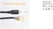
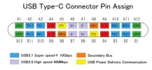
The camera's USB-C port uses 3 pins to receive Y, R and B.
Both Yellow and Red must have voltage to turn ON the camera, without Yellow the camera with the HK- cable will not start.
As long as Yellow and Red have voltage, the camera will continue recording as normal.
Once the Yellow ACC voltage is OFF and the Red voltage stays ON, the camera will switch to parking mode and will return to normal mode if the ACC is turned ON again.
(Not that there is almost no current going thru Yellow wire).
Again, all the magic happens inside the camera (power controller/processor, etc), not in the HK-.
In fact, for My DIY LTO battery I am using 2 buck converters to replace HK- voltage regulator, and when using power stations to power the camera, I use 5V directly from the USB-A port, so I don't need the HK- voltage regulator, and I remove it.
See the link:
The HK- is simply a step-down voltage converter(s) with a low voltage shutdown function.
It does two things: it converts the ±12V/24V to the 5.2V required by the camera, and it cuts off the power at the selected low battery voltage setting.
It has 3 wires IN (yellow, red and black) and 3 wires OUT (yellow, red and black)
Yellow is ACC voltage, Red is constant voltage, and Black is ground.
The camera's USB-C port uses 3 pins to receive Y, R and B.
Both Yellow and Red must have voltage to turn ON the camera, without Yellow the camera with the HK- cable will not start.
As long as Yellow and Red have voltage, the camera will continue recording as normal.
Once the Yellow ACC voltage is OFF and the Red voltage stays ON, the camera will switch to parking mode and will return to normal mode if the ACC is turned ON again.
(Not that there is almost no current going thru Yellow wire).
Again, all the magic happens inside the camera (power controller/processor, etc), not in the HK-.
In fact, for My DIY LTO battery I am using 2 buck converters to replace HK- voltage regulator, and when using power stations to power the camera, I use 5V directly from the USB-A port, so I don't need the HK- voltage regulator, and I remove it.
See the link:

Here are slides showing wire work and connections (you will need two USB-A cables (preferably 20AWG) to splice wiyth HK4)

Last edited: