70mai Dash Cam Battery Pack (7500 mAh) - Test / Review - RCG

rcg530

Well-Known Member
Joined
Jan 23, 2021
Messages
2,716
Reaction score
4,554
Location
California
Country
United States
Dash Cam
70mai, BlackVue, Thinkware, Vantrue, Vueroid, VIOFO
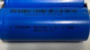
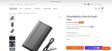
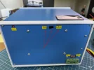
70mai sent me a test/review sample of their new 7500 mAh (96 Wh) Lithium Iron Phosphate (LiFePO4) battery pack. I've started testing this battery pack (limited tests so far).

Specifications listed on the box:
  • Model: BL96NNX
  • Nominal Voltage: 12.8V
  • Rated Capacity: 7500 mAh
  • Rated Energy: 96 wh
  • Nominal Capacity: 7600 mAh
  • Limited Charging Voltage: 14.6V
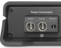
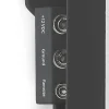
  • DC Output (XT30): 11.2 - 14.2V 2A Max
  • Type-C Output: 5V 2.4A Max
  • DC Input: 11.2-30V 11A Max
  • Charging Temperature: 0°C ~ 45°C (32°F ~ 113°F)
  • Discharge Temperature: -10°C ~ 60°C (14°F ~ 140°F)
Additional Specifications In User Manual:
  • Battery Type: LiFePO4
  • Storage Temperature: -10°C ~ 60°C (14°F ~ 140°F)
  • Max Cigarette Lighter Power Adapter Charging Amps: 7 Amps
    • Charging Time: 90 minutes
    • The CLA charging cable is not included in the box (optional accessory)
  • Max Fuse Box Charging Amps: 11 Amps
    • Charging Time: 60 minutes
  • After 2000 complete charge/discharge cycles
    • Battery retains 70% of its original capacity
Battery Pack Size
  • 22 CM x 12 CM x 3.5 CM (8.67" x 4.72" x 1.38")
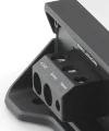
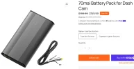
What's In The Box
  • Battery Pack
  • Fuse box charging cable
  • Parking surveillance cable adapter
    • 3-wire cable that is to be spliced with dash camera's hardwire cable/adapter/kit
    • Each wire also has a 1-wire lever connector nut [no soldering required]
  • Type-C to Type-C output power cable
  • Four fuse taps
  • Four 20A fuses [one for each fuse tap type]
  • Cable ties
    • The box I received only contained one Velcro cable tie
  • Two Velcro tape strips
    • Can be used to secure the battery pack to the installation location
  • User manual
Initial Thoughts
  • Charging Power Choice
    • Hardwire vs Cigarette Lighter Adapter (CLA) - Purchase Time Decision
      • The battery pack comes with one charging cable based on your purchased time decision.
    • Hardwire Charging Cable
      • Stated charging time from 0% to 100% is approx 60 minutes
      • The charging cable contains 16 AWG wires.
        • This seems a bit undersized for the number of max charging amps (11). With the ambient air temperature during my charging test being 83F, the charging cable reached a max of just under 100F during the high amp draw portion of the charge cycle.
        • 1727818463061.jpeg
          1727818564525.jpeg
      • The installer is expected to source the constant (VCC) power supplied to the battery pack from a fuse tap
      • Four different fuse tap types are provided in the box - each having a 20 Amp fuse installed in the accessory device (top) fuse slot
        • The battery pack is rated at a max of 11 Amps, so the 20 Amp fuse seems too high of an amp rating (15 amp would be sufficient)
        • Adding a 11 amp load to a pre-existing fuse box circuit may be overtaxing the wiring providing power to the fuse box fuse socket if the pre-existing item(s) powered by that fuse box fuse socket are consuming a vast majority of the current capacity of the circuit.
      • The installer is told to wrap the accessory power sense wire (ACC) around a leg of the fuse in the fuse box (major fail!)
        • You never wrap a wire around a fuse leg since it my expand the contacts in the fuse box fuse socket (major fail!).
        • The installer may not select the side of the fuse box fuse socket that will be protected by the fuse (major fail!).
        • There should be another fuse tap provided in the box for the ACC wire to be properly installed into the fuse box.
    • CLA charging cable
      • Stated charging time from 0% to 100% is approx 90 minutes
      • Vehicle's Cigarette lighter (power) port must provide switched power
        • The vehicle's power port must turn off the power to this port when the vehicle's ignition is turned off.
    • Switching from "Fuse Box" charging to "CLA Charging"
      • There is a process identified on page 5 of the user manual that you must perform to "unlock" the battery pack so that the battery pack can be successfully charged using the CLA charging cable.
  • Multiple references to XT30 connectors when the battery pack uses MR30 connectors
    • There are multiple places in the product documentation that states the battery pack has XT30 connectors.
    • It actually has MR30 connectors.
  • First Time Charging Test - Fuse box charging cable option
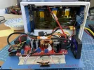
    • I used a DC power supply set to 14.2V with a maximum of 10.2 A (max for the DC power supply)
    • The evening before the test, the battery pack had been fully discharged using a DROK USB load tester
    • Maximum Amp Draw
      • Occurred at 49 mins 26 seconds [click on picture]
      • Output
        • VCC = 14.20V
        • ACC = 14.07V
      • Charging (Input)
        • Amps = 8.742 Amps
      • 1727821880685.png
    • Charging Progress
      • Start
        • Fully discharged battery pack
        • Output
          • VCC = 0.0V
          • ACC = 1.7 mV
        • 1727822618601.png
      • First power sent to dash camera
        • At 2.6 seconds, the output (dash camera) VCC and ACC power started receiving power
        • Output
          • VCC = 13.78V
          • ACC = 13.87V
        • Charging (Input)
          • Amps = 2 mA
        • 1727822859622.png
      • Approx 20 second delay before charging starts
        • At 22.2 seconds, the battery pack starts drawing charging power from the DC power supply
        • Output
          • VCC = 12.02V
          • ACC = 11.93V
        • Charging (Input)
          • Amps = 3.258 Amps
          • Amps ramp up to 7.252 Amps within 5 additional seconds
        • 1727823163158.png
      • 25% Charge Level
        • At 15 minutes 9 seconds, the battery pack reached a 25% charge level
        • Output
          • VCC = 13.85V
          • ACC = 13.73V
        • Charging (Input)
          • Amps = 8.555 Amps
        • 1727823493736.png
      • 50% Charge Level
        • At 29 minutes 23 seconds, the battery pack reached a 50% charge level
        • Output
          • VCC = 13.92V
          • ACC = 13.80V
        • Charging (Input)
          • Amps = 8.588 Amps
        • 1727823665394.png
      • 75% Charge Level
        • At 43 minutes 34 seconds, the battery pack reached a 75% charge level
        • Output
          • VCC = 14.05V
          • ACC = 13.93V
        • Charging (Input)
          • Amps = 8.669 Amps
        • 1727823938128.png
      • 100% Charge Level
        • At 59 minutes 3 seconds, the battery pack reached a 100% charge level
        • Output
          • VCC = 13.86V
          • ACC = 13.89V
        • Charging (Input)
          • Amps = 6 mA
        • 1727824170485.png
 
Last edited:
Yes the thin cable also worried me a bit, i understand a acquaintance of mine might have some of the plugs that the 70mai power pack use, if that is the case and i can get one i think i will make a new charge wire.
It would not be a big problem for me with the skills / and tools i have.
 
The installer is told to wrap the accessory power sense wire (ACC) around a leg of the fuse in the fuse box (major fail!)
  • You never wrap a wire around a fuse leg since it my expand the contacts in the fuse box fuse socket (major fail!).
  • The installer may not select the side of the fuse box fuse socket that will be protected by the fuse (major fail!).
  • There should be another fuse tap provided in the box for the ACC wire to be properly installed into the fuse box.
Yikes!
Multiple references to XT30 connectors when the battery pack uses MR30 connectors
  • There are multiple places in the product documentation that states the battery pack has XT30 connectors.
  • It actually has MR30 connectors.
Yes, these MR30 connectors are a pain in the @ss.
They are so small there are very difficult to unplug.
Every time I need to unplug the input / output I think I’m going to rip the tiny 16AWG wire out of the MR30 conector.
I told the 70mai rep in January these MR30 connectors were a mistake, and to use the much larger XT60 connectors found on the EGEN packs.
The XT60 also allow 12AWG wire.
The MR30 connectors only allow 16AWG wire.
The 70mai rep told me the first gen pack will use MR30 connector to keep cost down.
What I would like is for all battery packs to ditch any connector, and use bare wire terminal like car audio amplifiers.
This way the user can supply their own 12AWG 100% OFC pure copper power & ground wire, instead of the included (cheap & too thin) 16AWG CCA copper clad aluminum.
See attached photos.
100% Charge Level
I do like how the pack can fully 100% charge in the claimed 60 minutes with hardwire configuration.
I remember the PowerCell 8, and B-130X taking much longer than the claimed hardwire charge time.
Let me go look at my PC8 testing thread to confirm.
-
I have attached two photos of the 70mai's LiFePO4 cells.
 

Attachments

  • 1.) .webp
    1.) .webp
    107 KB · Views: 134
  • 2.) .webp
    2.) .webp
    173.7 KB · Views: 149
  • 1 .webp
    1 .webp
    82.3 KB · Views: 133
  • 2 .webp
    2 .webp
    15.5 KB · Views: 110
  • 3 .webp
    3 .webp
    9.1 KB · Views: 124
Yes the thin cable also worried me a bit, i understand a acquaintance of mine might have some of the plugs that the 70mai power pack use, if that is the case and i can get one i think i will make a new charge wire.
It would not be a big problem for me with the skills / and tools i have.
Even if you get a hold of some MR30 connectors the internal lugs only accept 16AWG wire.
So you will have to trim down 12AWG wire a bit, and stuff them through the clip piece before, and after soldering the wires in place.
This is why I have not purchased MR30 connectors to make my own 12AWG charging cables like I did for the PowerCell 8, and B-130X.
 
The MR30 is probably OK for powering the dash cam, but for charging they should have gone with the XT60I connector, using the middle pin for the yellow trigger.
I guess the limiting factor is the small case size.
I use the MR60 to charge my DIY batteries, it is easy to work with, but not available with flanges for mounting on a case, so I have to route power wires through o-ring/grommet.
 
The MR30 is probably OK for powering the dash cam, but for charging they should have gone with the XT60I connector, using the middle pin for the yellow trigger.
Yes.
The B-130X uses the XT60I-F connector for the Cigarette Lighter Charge Cable.
It uses the 3rd pin to let the pack know it’s being charged with the CLA cable, and not the hardwire cable, and drops the charging current from 9 Amps to 5 Amps.
See attached photo stolen from RCG530’s thread.
 

Attachments

  • charging_power_cables.webp
    charging_power_cables.webp
    93 KB · Views: 148
70mai battery pack now for $159,99 Fuse box solution or $151,99 cigarette solution in their online shop (only US store, not Europe).
 
Last edited:
70mai battery pack now for $159,99 Fuse box solution or $151,99 cigarette solution in their online shop.
Where?!
On the EU site it is 235 euros!!!
 

Attachments

  • 1000004700.webp
    1000004700.webp
    43.1 KB · Views: 96
It is on the US store, unfortanely not the Europe store.
 

Attachments

  • Screenshot_1.webp
    Screenshot_1.webp
    107.7 KB · Views: 100

Attachments

  • $152 .webp
    $152 .webp
    59.3 KB · Views: 160
  • $160 .webp
    $160 .webp
    69.2 KB · Views: 134
This is probably due to their Fall Sale which they were advertising since 2 days ago.
 
I received two cigarette lighter adapter (CLA) cables from 70mai for their dash camera battery pack. Last night, I performed the "switching charging method" setups outlined in the user manual to inform the BMS to allow the battery pack to be charged by a 2-wire cable from the CLA cable. Since there is no third wire providing the "ACC In" power to the battery pack, the BMS need to know to ignore the fact that the "ACC In" power will not be provided when it needs to charge when using the CLA cable. The cigarette lighter port / power port the CLA is plugged into must proved switched/accessory vehicle power. The 70mai battery pack will turn on/off the "ACC Out" (going to the dash camera" based on whether the CLA is receiving charging power from the vehicle.

1728693567805.webp

I can see this method of switching charging modes to use a CLA cable being a potential problem for some users. It requires somewhat precise timing of each step to successfully complete the switchover. I'm assuming that switching from CLA charging mode to "fuse box" hardwire charging mode will only require using the 3-wire charging cable. When the battery pack sees power on the "ACC In" wire, it should know it's using the 3-wire charging cable. I will test that switchover at a later date.

When the battery pack charging method is switched to use the CLA, the BMS limits the maximum amp draw by the battery pack while charging. I drained the battery charge level to just below 75% when I switched the charging method to the CLA cable. The maximum amp draw occurs shortly before the battery pack is charged. In my test, the max amp draw was 5.847 amps @ 14.2V. I used a 3157 incandescent bulb as the load on the battery pack, but I only used the taillight filament which draws 0.650 amps according to the DC power supply's display.

I'm running a battery drain down test using the same 3157 bulb and timing it. Once the battery pack has been fully drained, I'll run a full charge cycle using the CLA cable.

Screenshot of the max amp draw using the CLA cable:
1728693690857.webp


The max amp draw observed while charging the battery pack using the 3-wire charging cable (same incandescent bulb "load") was 8.730 amps @ 14.20V

1728694131081.webp
 
....
I can see this method of switching charging modes to use a CLA cable being a potential problem for some users. It requires somewhat precise timing of each step to successfully complete the switchover. ...
This is not a potential problem but a real problem in my opinion, most people don't actually read the manuals when buying a new product, let alone read them 2 years later when for some reason they decide to move from a fuse box to a CLA.
They will most likely be passing a lot of current through the CLA, potentially burning CLA circuit/wiring.

The worst part is that this is a completely unnecessary complication, I'm not sure why 70mai chose this process? When it's so easy to control the current with a switch.

The current is usually controlled by a resistor, all CC CV converters/chargers use an adjustable resistor to control the constant current.
For my first DIY LTO battery I added a second adjustable resistor in parallel with the original CC adjustable resistor and a switch to turn it on or off. So now I have two selectable charging current values adjusted to my needs.
 

Attachments

  • Additional Current Resistor and switch.webp
    Additional Current Resistor and switch.webp
    239.2 KB · Views: 106
  • Selectable Current Switch.webp
    Selectable Current Switch.webp
    84.4 KB · Views: 134
They will most likely be passing a lot of current through the CLA, potentially burning CLA circuit/wiring.
That should not happen if the battery pack is in "fuse box" mode and a CLA is plugged into the battery pack for charging. The CLA cable does not provide any "ACC In" power to the battery pack. The battery pack will sit there doing nothing until the user realizes they must perform the charging changeover steps in the user manual (page 5 in the printed user manual and page 6 in the PDF version of the user manual).
 
I put the 70mai battery pack through its paces by fully charging it using the cigarette lighter adapter (in this video I do that to top off the charge of the battery pack) and then I perform a full discharge of the battery pack using a 3157 incandescent taillight filament as the "load" on the battery pack.

At the end of the video you'll see the estimated capacity available to the light bulb while discharging the battery pack.

There is a quick reduction of the VCC [out] voltage from the battery pack after the charging power is removed. After about 6 minutes the VCC [out] voltage stabilizes at 13.16V/13.18V range.

The VCC [out] voltage level has a slow linear reduction over the 9 hours when it reaches 12.85V which when the battery pack charge level is just above the 25% level. The rate of voltage decay starts ramping up as the VCC [out] reaches 12.75V just before the 10th hour. When the VCC [out] reaches 12.60V around the start of the 11th hour, the rate of voltage level decay increase sharply. At 11.5 hours, the VCC [out] voltage level dropped to 12.27V. Over the final 30 minutes of the test, the VCC [out] voltage level decays are a rapid rate going from 12.27V to 11.19V in that thirty minute period. If haven't collected the voltage levels from each one-minute time period of the test since that's a lot of analog-to-digital watching/typing, but if enough people are interested, I can gather that data.

 
That should not happen if the battery pack is in "fuse box" mode and a CLA is plugged into the battery pack for charging. The CLA cable does not provide any "ACC In" power to the battery pack. The battery pack will sit there doing nothing until the user realizes they must perform the charging changeover steps in the user manual (page 5 in the printed user manual and page 6 in the PDF version of the user manual).
Oh, good to know, I must have missed that.
But still, the process is, to say the least, inconvenient.
Especially when they had 2 different and both better options implemented in competing batteries.
 
Charging Bootstrap Issue - 0% Starting Charge Level

I've run into an issue twice where the 70mai battery pack won't provide proper VCC Out / ACC Out voltage and it won't start charging the battery pack.

I'm attempting to test how the battery pack's BMS handles the situation of a vehicle that is parked for an extended period of time and the battery pack drains to what the BMS determines to be 0% charge level which means the BMS turns off the VCC/ACC output power. The battery pack remains in that state for some number hours/days. The user attempts to start their car and the vehicle provides charging power via the "fuse box" hardwire cable or the CLA charging cable. The "load" in my test case is the taillight filament in a 3157 incandescent bulb. It consumes around 600 mA which will vary based on the voltage level supplied by the battery pack's VCC output wire.

Based on my previous testing, the BMS will turn off VCC/ACC output power to the "load" when the VCC voltage level dips to 11.19V.

Last Friday night and Saturday morning, I ran a discharge test of the battery pack (see video in post 17). I left the battery pack in the same state (switch in "on" position, load connected, 0% charge level [no status LEDs on], no charging power from CLA cable) until this morning. I was attempting to time the charge cycle of the battery pack with the CLA charging cable providing the charging power when I ran into the same problem. The battery pack got stuck again when first having charging power supplied to it. The VCC & ACC output voltage levels were in the 6.7V to 7.0V range for a short time and then voltages dropped to the mid 4-volt range. Once again, I had to remove the load from the battery pack before it would start charging.

I've supplied this info to 70mai and I'm waiting to hear what the response is to this issue.

Here are two screenshots from my charging attempts showing the odd voltage levels that were provided by the battery pack until I disconnected the load:

Fuse Box Cable vs CLA Cable
70mai_fusebox_charge_attempt.webp20241014_cla_charge_attemp_low_voltage.webp
 
I gathered the VCC output voltage values over the discharge test I ran last week and created a chart of the VCC voltages.

Click on thumbnail to see full chart.
1728936692316.webp
 
Back
Top