DC's DC DC-to-DC build thread

DigitalCorpus

Active Member
Joined
Oct 17, 2023
Messages
111
Reaction score
71
Location
California
Country
United States
Dash Cam
Vantrue N4 Pro
I'm sorry for pinging you both, @GPak & @Agie, but I want to thank you both for conversing with me on this topic earlier on.

Honestly, I wasn't planning on a title that was ambiguous/clever/redundant/dumb/smart. Hi, I'm [DigitalCorpus] starting my build thread in spirit to what GPak has done in his thread, to connect my dash cam to a LiFePO4 battery (house battery), which will need a DC-to-DC (direct current to direct current) regulator between my DIN H5, BCI Group 47 AGM starter battery and a 100 Ah LiFePO4 house battery. At worst, a 100 Ah is ~40% more capacity than I'll need, and at best ~30% of maximum capacity of it used. Most people will not need to go to the lengths I will be doing here, and if you're looking for something simple, head back to the thread I linked above. You'll need an intermediate electrical knowledge, and be comfortable enough in to know that crimped connectors are better than soldered connectors depending on use case, or have enough money to pay someone who knows this.

I'm going to be linking to many specific products through the course of this thread. A listing, link, or mention of a product is an endorsement or guaranty of the product; though it may be an endorsement of the technology the product represents.

Background​

I live in Southern California (colloquialy known as SoCal) and have a penchant for electronics and technology. I have moved from a '97 VW Passat TDI to a '23 Honda Civic 1.5Tand decided to pick up a dash cam. For the past 15+ years, half of my driving takes place as night and for that reason, I chose a Vantrue N4 Pro in order to read license plates, otherwise it is almost useless half of the time. Unfortunately, Vantrue hasn't or cannot optimize the boot time of the N4 Pro (N4P hereon) nor its power usage so the need for an auxiliary power source is needed if I want it to record for more than when the *engine* is on.

Intended functionality​

  • Power the N4P in Time Lapse or Parking modes
  • Sustain the starter battery during Auto Idle Stop (more details later)
  • Jump the starter battery from the LiFePO4 battery
  • Selectively remove the LiFePO4 from the factory electrical system

Fun functionality​

(Used to field ideas and let them live or die w/o spending money on them)
  • Power a GSM/LTE booster/repeater
  • Galvanically isolate the LiFePO4 battery
  • Power 1 kW, 2 kVA inverter (if this exists, I don't know the realm of specs)
  • Jump the starter battery of a different car from the LiFePO4 battery, directly or indirectly
  • Power auxiliary lighting switched with ignition
  • Data logging of LiFePO4 & AGM usage
  • Kill switches that function for safety and anti-theft
  • Low power SBC (single board computer) for possibly remotely connecting into my N4P and downloading the footage as a backup

Where did I start & why this route?​

I started with GPak's thread. The economics of the batteries for powering dash cams during parking mode is poor and causes these types of pack to have fairly high prices. I wish these companies the best and they have to make a profit in order stay in business. I am by no means maligning them as the packs are straight forward in their use case for those who want one and need just a little power. If you want to save money and are able to DIY some things, then I'd suggest going back to GPak's thread. If you just want to "DIY" it and build out a dual battery system, you're going to dip your toes into the high power car audio and/or the overlanding crowds. Everyone's car/truck/van/UV/RV is different and what they want the power for is similarly different.

I'm not chasing decibels and I'm not camping on cliff faces 'cause I'm in a hatchback. However, I'm in a unique area of the US that has beaches a couple hours away and Death Valley on the other side of the mountains to my north. Most of the reason for starting the above "thought trek" is knowing how much power the N4P needs, though if I'm gonna have a battery this big, It might as well power more than just my dash cam. I've been around a few hybrids and they can have a dandy feature of using the starter battery down to a point, turning the engine on and charging it, then turn the engine off again, ad infinitum. My ICE car only does this cycle once and I'm keenly interested to see if I can extend the duration, directly or indirectly. Hard to jerry rig in a power station for this type of loading, and charging.


Just in case anyone is interested in following along and is new to electrical power, here are some terms I may be using along the way:

DC - Me, or dash cam, or direct current. Take your pick.​
Breaker - Circuit breaker. Safety device for electrically breaking a connection between two points. This can be reset physically and the break is not permanent.​
Fuse - Like a breaker, but one time use.​
Cap - Depends on context: short for capacity, referencing the [electrical] current capacity of the battery OR for for capacitor, a passive electronic device for holding electricity.​
Cell - What most people call a battery. The is the simplest, physical part of a battery. If you see voltages referenced below 5 V, we're talking about [battery] cells.​
Battery - A collection of cells in series and/or parallel to meet a standard voltage and/or capacity for an electrical system standard.​
AGM - Absorbent Glass Mat type of lead acid batteries. More expensive than a regular flooded lead acid battery, but still lead acid.​
LiFePO4/LFP - Lithium (Li) Iron (Fe) Phosphate (PO4), a widely popular lithium battery chemistry that prioritizes safety over power density and discharge current.​
Overland(ing) - Point to a spot on a map and drive there while being self-sufficient. Spend the night, or the week.​
Starter battery - The battery, usually lead acid, used for turning over your engine to start it. Practically useful for short term, low DoD usage.​
DoD - Depth of Discharge, how much your discharge a battery​
House battery - One of a few ways a dual battery system can be setup, and this battery, usually LFP, is for longer term power for use when the engine is not running.​
ODM - Original Device Manufacturer. Common is electronics, like laptops or power supplies, but also here with LFP batteries.​
BMS - Battery Management System, provides the basic electrical system mechanisms for operating a battery.​
Galvanic Isolation - A term used in electronics meaning that DC cannot flow between different sides that are isolated using this means.​
Reverse Charging - Jump starting​
Shore power - AC power input to charge a dual battery system.​
TEC - Thermoelectric cooler, aka a Peltier device, uses some fun material properties that can turn voltage into a temperature differential, and vise versa.​
NO & NC - Normally Open and Normally Closed terms for the state of a relay when power is not applied to the coil​


Edit Reason: Moved Parts to post 2
 
Last edited:

Collection of Parts & Functions​

(updated as I progress)
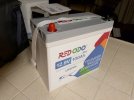
  • 12.8 V, 100 Ah "mini" battery in a case ~35% lower volume than traditional 100 Ah LFP batteries
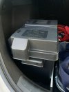
  • NOCO HM306BKS battery box
    • Case to hold the battery to keep it safe and you/things safe from it.
    • Affixes the battery to the vehicle to avoid it relocating during bumps, cornering, or other (un)intentional forces.
    • Additionally, safeties and various DC outputs can/are commonly added to the box.
  • DC-to-DC Converter, Renogy 40 A, non-isolated
    • Due to the fact that alternators/generators have an RPM-dependent output curve in for their amperage rating and LFP batteries have low internal resistances compared to lead acid, this is a requiredelectrical device used to prevent releasing the magic smoke from expensive things.
      • If the magic smoke is still in the thing, it works. If it isn't, thing no worky.
      • With LFP batteries, if not installed properly, the whole car can release its [expensive] magic smoke.
        • I'm not fear mongering. A healthy dose of respect is due.
    • These can be galvanically isolated, but not usually, and the one I chose is not.
    • These can reverse charge the starter battery, but that isn't always a thing, and the one I chose does not have this feature.
    • Sometimes these support dual inputs: alternator/generator and solar panel(s)
    • Sometimes these support AC input, "shore power", and are triple input
  • Crude, at-the-limit temperature regulation
    • A TEC can cool or heat and but will have to fall back to "off" is the demand is too high and not drain the LFP
      • Activates near limits: provide heat @ <= ~5 °C, remove heat @ >= ~40 °C
    • Rough metrics from datasheets show I'll need a 100-250 W TEC, and driven at 5-30 W

Anyhow, I've collected the first two items and need to determine which DC-to-DC converter(s) I'm going to pick. I might need 2, one fancy one for charging the house battery and then a lower power one for reverse charging the starter battery. If I go a dual converter setup, then, I will have to use some staged relays, mechanical or solid state, to ensure that both converters are not powered at the same time, thus having their operation mutually exclusive, as apart of safe operation.


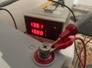
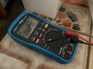
This is a 30 V, 10 A, linear, programmable bench power supply, making it an expensive charger. I charged it to 14.2 V overnight and later did tests at 14.4 V & 14.6 V to see how the BMS would behave; more or less more power was not accepted after about 5 seconds. Battery terminal torque spec is 8 N*m, aka 5.9 ft*lbf, aka 70.8 in*lbf. The manufacturer says the terminals are silver plated copper and the M8 bolts are stainless steel. The M8 bolts are way more magnetic than expected for stainless steels and the terminals are not magnetic. A knife nicking them isn't showing any yellow metal (e.g. copper, brass, or like alloys) underneath (so it is really thick silver plating maybe?) and its not ductile enough to be aluminum. The toque spec aligns with expected yield strength of copper; this is my torque spec sanity calculator when I've worked on modifying engines.

IMG_6227..jpg IMG_6228..jpg IMG_6265.JPG


Internal dimensions are ~7.5" x ~10.5" x 11" while the battery is ~5.25" x 10.25" x 9", so yeah, it is a bit oversized, but it is the smallest box I could find that would fit.

IMG_6235..jpg IMG_6242..jpg IMG_6237..jpg


Once I know what current I'm pushing through via the DC-to-DC converters, I'll be able to size wire, breakers/fuses, bus bars et al.


Edit Reason: Move Parts over and update
 
Last edited:

Renogy 40A, DC-to-DC charger, RNG-DCC1212-40, Teardown & Cursory Overview​

So I took these photos about 3 weeks ago, and apologies for not getting them posted sooner. I've already clocked the interior temperature of my car easily reaching 45 °C so I'm concerned the charger won't play nice during SoCal's summers as it is rated for a max of 50 °C and the manual words it such that it may trip OTP and just shut off. The manual states the charger is rated for a 500 W, more on this later. There are many many other chargers on the market and few have active cooling (fans). This doesn't automatically make the charger better, but does allow for the possibly better than others. IIRC, Victron Energy's chargers actually have a de-rating spec for thei charger and have massive convectively cooled heatsinks. And then there are the unknown-ODM chargers from LiTime, Power Queen, ATEM Power, and then of course REDODO. No problem with these, but I question how long they will last at a 40 A output in elevated temps, oh and I cannot find a worthwhile datasheet or manual for them to give tech specs on them. Anyhow, photo time.

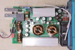
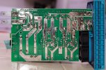
Front & Back PCB shots​

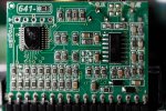
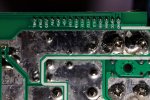
Note, I flipped the top PCB photo horixontally for the sake of those playing along. Okay so, it's not great that they are using solder on the main traces to increase their current capacity, but it is a legit method. I'm annoyed that the board still has flux because it is exposed the to environment and can lead to reliability problem down the road. I am happy with the divider they put in to segment the airflow through the case. Now despite the fans, I do want to note that the fans are exhaust, not intake so I'm really curious as to their effectiveness for the heatsinks, but the spacing for all of the components is done well for low speed air cooling. Most of what is seen if passive circuitry. I do not know the material of the bus bars used for input & output, and a NO 40 A relay is used to switch the output on/off. I beleive the pair of smaller chokes are for output smoothing, but I don't know the topology that was used here.
Renology._OB_9996.jpg Renology._OB_9994.jpg

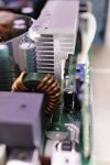
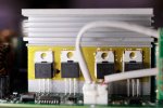
Cooling Active Components​

I actually saw this bit "first" when openning the case because thermal pads act like glue to a degree, thus it is normal for them to tear when separating the mating places. Anyhow, yeah, dissapointment set in becase that's what, like 1/3rd of the thermal pad making contact with the outer case for transfering heat off of the MOSFETs. The other heatsink I didn't photograph and only has the rectifying diodes on it, nothing note worthy and by the lack of a thermal pad on it, requires less thermal dissipation. Anyhow, I thought it was odd to have a thermal on the MOSFET heatsink, then I saw the polyamide, aka Kapton, tape. It is an electrical insulator because the tabs on the 'FETs are electrically hot. Polyamide tape is an excellent thermal isolator too; you can use it as a barrier when you do hot air rework. This right here, even without thermal testing, is why I bet the operating temperature limit is 50 °C. The heatsink is electrically floating. I know there are some off the shelf materials that are designed for electrial isolation and thermal transfer becase this type of issue is common, though it is more expensive to impliment.
Renology._OB_0002.jpg Renology._OB_0016.jpg Renology._OB_9981.jpg

Control Componentry​

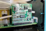
I'm in no way interested in trying to reverse engineer these control boards, and as such I'm only photographing on side of them, but the pinouts are labeled, which is appreciated. The first board appears to be most of the regulator's control, which is driven by a Microchip MCU (ICSP header above it). The Chinese on the top right are for Voltage & Current and are denoting the POTs (potentiometers, i.e. variable resistors), which I assume are for the output's current & voltage calibration. Anyhow, both boards have a conformal coating, which is likely due to the fact that, drumroll please, they're exposed to the evironment. The only electrical safety protections are OPP and OLP, which are the same, Over Power Protection and Overload Protection. More on this later. Some MCUs have internal temperature sensors so it is possible this charger has temperature monitoring and a derating curve, but it is not published.
Renology._OB_9983.jpg Renology._OB_9988.jpg Renology._OB_9973.jpg Renology._OB_9991.jpg

Output Ratings​

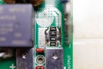
The output current is measured using 4, 5 mOhm shut resisitors in parallel, aka, a 1.25 mOhm shunt. Its crude. I don't like it, but ces't la vie. I do note the unpopulated outpt capacitor. There is another for an X/Y cap between the 3 output caps and the transformer on the left, denoted as C22. Renogy rates the output at 50 mV output ripple, which should be for that complete 40 A output. Now some time for maths, given that this charger is rated for 500 W and 40 V, we have some details that should be noted. A lot of these chargers are designed to work with both common lead acid types and some lithium chemistries. This means it will work for SoC voltages from ~11.6-12.7 V for lead and 12.9-13.6 V for LFP. With a 500 W, 40 A limit, this puts us at 12.5 V, which translates to 90% SoC for lead and ~15% SoC for LFP. In other words, if you go with a lead acid chemistry you'll get the full 40 A out of the charger, but if you go LFP, you're going to be limited to 34-35 A.
Renology._OB_0008.jpg

Alright, well, since I was planning on using the LC switch on this charger to limit the current to 20 A for the sake of the battery, and power dissipation on a resistive load is proportional to the square of the current output. Combined with the charger's rated at 90% efficiency, I think things will be fine. Obviously I've voided the warranty, but I intend to clean up the extra flux residue and improve the lackluster cooling.
 
Last edited:
post 3 - reserved for 10K character limit (I can delete if this is frowned upon here)
 
Last edited:
post 4 - reserved for 10K character limit (I can delete if this is frowned upon here)
 
Last edited:
post 5 - reserved for 10K character limit (I can delete if this is frowned upon here)
 
The economics of the batteries for powering dash cams during parking mode is poor and causes these types of pack to have fairly high prices.
Bingo, these $3-400 100wh batteries are pathetic, nowhere near the capacity needed for everyday use and too slow to recharge imo.
I went with an ecoflow river2 power station and will use that to power my a229 pro, should be here soon, but now wondering if this isn't a better solution since i will still have to turn off my dash cam when i'm home to save power and turn it on when i leave. Since i only drive 30m a day i still might have to charge it fully once a week since it only charges at 100watts per hour and doesn't like sub zero temps.
Can these Red Odo batteries be charged and discharged at the same time? What charger will you be using in the car?
 
The M8 bolts are way more magnetic than expected for stainless steels
What do they say they are on the top?
Probably "8.8" if they are steel.
Would expect "A2" for stainless, but that is not magnetic at all!
 
Bingo, these $3-400 100wh batteries are pathetic, nowhere near the capacity needed for everyday use and too slow to recharge imo.
I went with an ecoflow river2 power station and will use that to power my a229 pro, should be here soon, but now wondering if this isn't a better solution since i will still have to turn off my dash cam when i'm home to save power and turn it on when i leave. Since i only drive 30m a day i still might have to charge it fully once a week since it only charges at 100watts per hour and doesn't like sub zero temps.
Can these Red Odo batteries be charged and discharged at the same time? What charger will you be using in the car?
Pathetic is the wrong word, or at least too strong of a word imho. Using the REDODO (yeah, they like all caps iirc) pack is like using any other battery, so if the net current is positive, the battery will charge. I have picked up a charger, but I don’t know if it’ll behave in the summer months because the documentation says it’ll shut off in an ambient environment of 50 °C. But it has active cooling, which is why I got it. Testing that in winter will be tricky.

My commute is twice that. Be mindful of that 0 °F temp as that is inherent of LiFePO4’s chemistry and you can only get around that with heating. I might add in 2 resistive heating elements to experiment with.

What do they say they are on the top?
Probably "8.8" if they are steel.
Would expect "A2" for stainless, but that is not magnetic at all!
They’re custom fasteners, 13 mm / 0.5” hex drive with a PH2 Philips drive in it too. Finish is darker than A2 stainless. They have a split ring lock washer sandwiched between the head and a standard flat washer. All 3 have the same finish so I’m thinking zinc or nickel plating, assuming the latter.


I need to source cable and determine how im getting it from the engine bay to the trunk. I have a good lead on some that’s half the going price, but that screams CCA conductors and not copper. Also 1/0 AWG cable is thick and I’m sizing it that way in case I ever do want to pump 100A from the house battery to the starter battery. I’ll be editing post 2 with more info over the next couple of weeks and likely adjust the title post due to the 10k limit. Stay tuned. I appreciate everyone’s interest.
 
They’re custom fasteners, 13 mm / 0.5” hex drive with a PH2 Philips drive in it too. Finish is darker than A2 stainless. They have a split ring lock washer sandwiched between the head and a standard flat washer. All 3 have the same finish so I’m thinking zinc or nickel plating, assuming the latter.
I don't think stainless steel is a good choice anyway, because the oxide layer that forms on its surface is non-conductive, a bit like aluminium bolts but not as bad. Nickel coated steel, coated with petroleum jelly to prevent corrosion is decent choice.
 
I have picked up a charger, but I don’t know if it’ll behave in the summer months because the documentation says it’ll shut off in an ambient environment of 50 °C. But it has active cooling, which is why I got it.
Which one? Just trying to get an idea here.
 
Last edited:
I don't think stainless steel is a good choice anyway, because the oxide layer that forms on its surface is non-conductive, a bit like aluminium bolts but not as bad. Nickel coated steel, coated with petroleum jelly to prevent corrosion is decent choice.
See, that’s the question I haven’t found decent guidance on. My thermal knowledge comes from computing and I understand why nickel plating is required for using galinstan-like alloys.

Lead posts have crap conductivity, zinc & nickel are about the same as well as brass, then you have the stainless steel families, and then you have aluminum. Nickel is preferred over zinc for mechanical durability when both are used for plating, brass is tough too, but about 20-30 % as conductive as copper. However, copper is ver ductile and soft and oxidizes easily, but not as rapidly as aluminum. And if the batter terminals are actually silver plated, stainless has is galvanically closer to it and will be the best pairing.

I can find nickel plated studs, whole zinc & zinc plated studs, and lead studs. Flooded lead acid and AGM batteries need lots of current for a brief duration so even low conductivity studs won’t matter much from the voltage drop & I^2*R losses. But lithium (all types, not just LiFePO4) can supply moderate current for long periods of time. I’m very curious on the contact resistance vs material resistance for the studs/terminals.

There is petroleum jelly and there are thread lockers made for use around electrical connections. Displace and prevent oxygen from penetrating and then I don’t have to worry about galvanic corrosion. More or less, my curiosity is piqued and I want to read up on this more.
 
Last edited:
That’s the idea. Somehow apart of “smart” alternators. Haven’t dug into this much yet. I do know my stock alternator is 135 A, and I can only estimate it’s output capacity vs RPM, and because of the auto idle stop, I suspect I do have this lead. I do have a couple factory places to put a switch or 5, to which I’ll may have a couple toggles for that and the LC (Limit Current, not Inductor Capacitor, e.g. LC tank circuit) I’ll have engaged normally to limit charge current to 20 A.
 
...the documentation says it’ll shut off in an ambient environment of 50 °C. But it has active cooling, which is why I got it. Testing that in winter will be tricky...
I cracked the case open to have a look at things and see what's what. Built to a price this is, but everything looks sound. It was really easy to identify the main sources of heat and why there is a 50 °C limit on ambient temperature. I'll photograph things and update post 2 after some sleep. I need to dig through a couple PDFs and take some measurements, but it appears to be relatively painless to upgrade the cooling performance to a notable degree. I only have 200 W of electronic loads, and the charger is capable of >500 W so I do not think I'm going to go to the trouble of trying to do A <-> B testing after modifications.
 
Update, photos and basic breakdown of the charger is in the third post. For lithium chemistries, consider the output of this charger to be 35 A, not 40 A, which is my largest takeaway.
 

Renogy 40A, DC-to-DC charger, RNG-DCC1212-40, Teardown & Cursory Overview​

Interesting, I was under impression that fancy brands like Renogy and Victron are like I-Phones inside, with build quality and components.
I am working on LTO battery pack, using cheap, off-the shelf, parts. The problem with LTO is that specialized chargers are not available, so I am using universal CC-CV, DC to DC converter/charger. I was worried about the quality and reliability, but now I am a little relived seeing Renogy being not that much different with components and quality.

Testing them for a couple of weeks now, so far so good
Here they are, rated at 12A, 20A and 40A:
https://www.amazon.com/gp/B098SVD2B8
https://www.amazon.com/gp/B0CGTBMNJQ
https://www.amazon.com/gp/B0C53B7KGY
 
Victron Energy I’d say is a boutique brand, where as ATEM Power, Power Queen, and Redodo are not. LiTine seems to cover the gamut a bit more than the others and it’s not a bad thing that they share an ODM for some of their packs. This happens in laptop computers for example with brands like Eluktroniks being a North American seller for the ODM Clevo and both are very rell regarded.

The converters you selected are step up only converters. They usually need ~2V of separation above the input voltage to work. AGM and flooded lead acid can have float voltages in the 14 V range, which can cause a problem here. The Renogy charger is a high current buck-boost topology, but customized for the application listed. A lot of people in audio or overlanding spaces still use lead chemistries so their current derating aren’t a terrible surprise, though I do plan on doing a charging test from a low SoC on my pack.

The problem here with cost is not far off from the PSU market for computers either. There is a hard time finding solid, inexpensive, safe designs with total capacities under 500 W. Economically, consumers have a hard time justifying the cost of quality products as they’d expect price to scale proportionally with max output, but that’s simply not the case. We’re kinda looking at the low end here. That rebadged charger that comes in 4 color schemes is a product of this type of economy. This charger I have is a step up over that, but not as boutique like Victron Energy is. Hope that provides some perspective and isn’t too rambly.
 
Interesting, I was under impression that fancy brands like Renogy and Victron are like I-Phones inside, with build quality and components.
I am working on LTO battery pack, using cheap, off-the shelf, parts. The problem with LTO is that specialized chargers are not available, so I am using universal CC-CV, DC to DC converter/charger. I was worried about the quality and reliability, but now I am a little relived seeing Renogy being not that much different with components and quality.

Testing them for a couple of weeks now, so far so good
Here they are, rated at 12A, 20A and 40A:
https://www.amazon.com/gp/B098SVD2B8
https://www.amazon.com/gp/B0CGTBMNJQ
https://www.amazon.com/gp/B0C53B7KGY
What are the SoC voltages for LTO, btw?
 
Back
Top