mister_rf
Member
- Joined
- Feb 24, 2013
- Messages
- 51
- Reaction score
- 60
- Location
- Bucharest
- Country
- Romania
- Dash Cam
- YI /GT300W / C1 / DIMIKA / E720 / MOBIUS / DVR207 / 808 # 18
I’ve had the DIMIKA for about a month now, just the other days I noticed that the red light comes on indicating the camera is in charging mode as per the manual, however no charging anymore. Apparently the camera It was working just fine connected to a USB cable.
I have carry out a hard reset of the camera by pressing and holding the RESET button. No success. I removed the battery, in order to do a reset. Same problems, the battery indicator never comes off. Did some checking around and measure the battery, it was not half-charged like it said it was supposed to be by keeping on charging a long period of time.
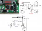
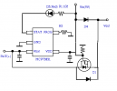
Before I had to start repairing this piece of electronic equipment, I first had to identify and compare components through web-research, in order to draw a minimal diagram of it. The following schematic diagram shows a circuit to generate the necessary LiPo battery charging.
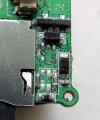
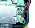
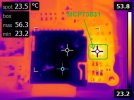
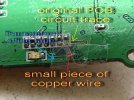
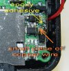
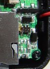
Based on that it was easy for me to find the faulty components on its printed circuit board. Sometimes, you can identify some bad components on a PCB just by looking at it. So I compared the previous circuit PCB photos I have taken with the actual ones, and I have discovered a small dark area on the surface of one of the ICs. The burn marks were due to overheating of the ICs.
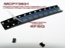
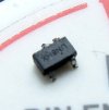
Circuit marking UN8HX.
This handy little IC will correctly and safely charge the Lithium Polymer batteries with power from a USB port or from a DC wall adapter. Max current is limited to 500mA . Requires almost no external components and will automatically select between internal DC source and the USB source if both are present.
I have carry out a hard reset of the camera by pressing and holding the RESET button. No success. I removed the battery, in order to do a reset. Same problems, the battery indicator never comes off. Did some checking around and measure the battery, it was not half-charged like it said it was supposed to be by keeping on charging a long period of time.
Before I had to start repairing this piece of electronic equipment, I first had to identify and compare components through web-research, in order to draw a minimal diagram of it. The following schematic diagram shows a circuit to generate the necessary LiPo battery charging.

Based on that it was easy for me to find the faulty components on its printed circuit board. Sometimes, you can identify some bad components on a PCB just by looking at it. So I compared the previous circuit PCB photos I have taken with the actual ones, and I have discovered a small dark area on the surface of one of the ICs. The burn marks were due to overheating of the ICs.

Circuit marking UN8HX.
This handy little IC will correctly and safely charge the Lithium Polymer batteries with power from a USB port or from a DC wall adapter. Max current is limited to 500mA . Requires almost no external components and will automatically select between internal DC source and the USB source if both are present.


