USB power bank as a backup to the car battery

There are 2 relays. The 12v from the car battery (power magic pro) triggers both relays. On the top relay, it redirects power to the dashcam from the car battery to the 5v -> 12v step up adapter when it doesn't detect 12v from the power magic pro.

Once the 12v power source from the car battery shuts off, the lower relay completes the circuit for the usb male cable to the 5v -> 12v step up. This tricks the USB battery into thinking that it was just plugged in and turns the USB battery on. Since the relay completes the circuit, the 5v to 12v step up is enabled and powers the dashcam plug at 12v.
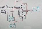
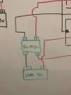
Might be better to use a dual pole relay, then you know that both will switch at the same time.
Also, since the relay coils are driven by a transistor in the PMP, might be a good idea to use a relay with a flyback diode, or add one to the design.
 
Thanks for your feedback Nigel. I'm not familiar with a flyback diode. Would this go between the PMP and the relay? The reading I did here: https://electronics.stackexchange.c...need-a-flyback-diode-with-an-automotive-relay indicates I may not need one because I'm using the same automotive relay with the built in protection diode.

I'll look into the DBDT relay. Is there any risk of damage in the current set up i have now? The second relay was mainly to enable waking up the power bank when the pmp cut off power. Without the relay, the USB battery stays asleep.
 
Last edited:
Thanks for your feedback Nigel. I'm not familiar with a flyback diode. Would this go between the PMP and the relay? The reading I did here: https://electronics.stackexchange.c...need-a-flyback-diode-with-an-automotive-relay indicates I may not need one because I'm using the same automotive relay with the built in protection diode.
The protection diode will be the same thing, although that is the wrong name since it does not protect the relay, it protects whatever is driving the relay coil from negative voltage spikes generated in the relay coil when it turns off, normally only needed if the relay is driven by a transistor. The diode connects between the 2 coil terminals on the relay to short circuit any negative voltage.
I'll look into the DBDT relay. Is there any risk of damage in the current set up i have now? The second relay was mainly to enable waking up the power bank when the pmp cut off power. Without the relay, the USB battery stays asleep.
Probably not any risk, although you haven't given the circuit diagram. The issue is that with two relays you can't be sure they will switch at exactly the same time, so you might be connecting the output of the two power supplies together, but I'm guessing that is not how you have it wired. A dual relay will switch both at the same time, and is generally neater since you can normally put some of the circuit on the relay itself.
 
I attached my circuit diagram. So the flyback diode is to protect the power magic pro from reverse voltage spikes. Is there a way to determine if the PMP already has protection against any voltage input? Also, if the relay has one built in, then that should be ok.

Both my relays are hooked up to the same 12v power source. Once the power is cut off they both switch.

Here's the relay. https://www.amazon.com/gp/B004Z0WMDY . The diagram has the diode and resistor symbols
 

Attachments

  • IMG_4847.jpg
    IMG_4847.jpg
    249 KB · Views: 19
Last edited:
Is there a way to determine if the PMP already has protection against any voltage input?
Unlikely to have protection, if used normally there would no need.

Also, if the relay has one built in, then that should be ok.
Yes.

No harm in having two protection diodes though, it just needs a normal diode connected backwards across the relay terminals.

I attached my circuit diagram.
Looks fine, only comment is that you shouldn't normally connect the voltage converter's input and output terminals together since it may disable the current limiting, however you will still have current limiting in the power bank so it should be safe.
 
Looks fine, only comment is that you shouldn't normally connect the voltage converter's input and output terminals together since it may disable the current limiting, however you will still have current limiting in the power bank so it should be safe.

The voltage converter's input is connected to the lower relay. The lower relay's purpose is to complete the circuit and trigger the USB battery to turn on. Without this, the voltage converter draws a tiny amount of current which the battery ignores and shuts down after a few seconds. Since the relay completes the circuit to the voltage converter, it makes the USB battery think that it was just plugged in and allows the USB battery to be awakened on demand.

The output is connected to the upper relay.

Can you clarify where you see the input and output terminals connected together? The ground is the only common thing connected.
 
Can you clarify where you see the input and output terminals connected together? The ground is the only common thing connected.
Exactly, you have shorted the two grounds together.
 
So like this instead?
 

Attachments

  • IMG_4848.JPG
    IMG_4848.JPG
    197.8 KB · Views: 18
So like this instead?
Yes, safest to assume that it has separate connections for in and out for a reason, might be just convenience, or maybe it measures the current through the 0v out, connecting them might even affect the stability of the output voltage.
 
Back
Top