Zenfox T3 Triple channel dash cams free test invitation, limited quantity

His picture is of a computer graphics card, not his camera. For illustrative purposes of how thermal pads (pink goop) is used.
I know that... I have opened many computers before. I frequent find those in tv boards like plasma TVs that are not longer made... and my point is that "that pink goop" is not the same material even though they share the same color
 
Secondary Questions:

@EGS did you have to remove the supercapcitor when taking your photo? Does it easily come out with a pin to motherboard?

TO EVERYONE: Does the tape going over the supercapacitor and covering up the fins of the heatsink affect airflow, too? Could this tape be routed vertically over the supercapacitor instead horizontally and covering the heatsink?

View attachment 52508
The capacitor wires are soldered to the board, and yes, I had to remove it off the sink. There is a double sided sticky foam pads holding it together .
 
I would step up your suggestion. If he really wanted the most optimal cooling, but didn't want to give up the heat shield placement, couldn't he setup things like so:

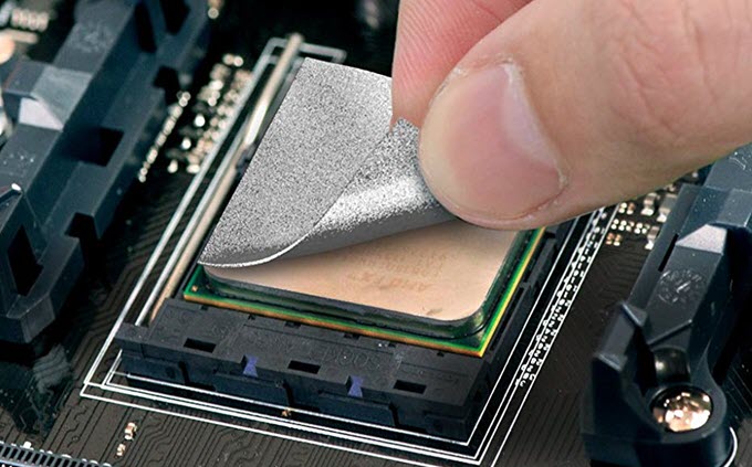
1. Copper plate on CPU with Artic Silver Thermal Paste
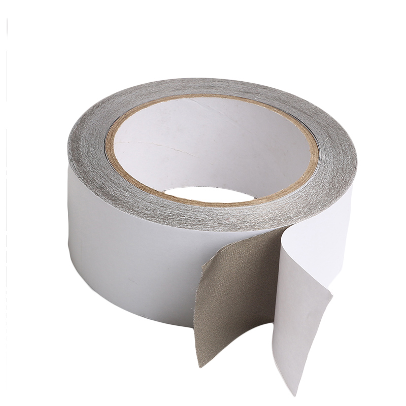
2. EMI Shield Affixed to Copper Plate with Artic Silver
3. Heatsink Attached direct to EMI shield with Artic Silver

Honestly, I agree this thing has a poor design and airflow. I've said that from the very beginning when I pointed out the device is overheating. No one believed me for a while, but now the facts are out, showing my assessment was correct.

I guess if Zenfox doesn't return here with an answer at some point, we all might resort to a few modifications on our own to see if we can get the camera stable. That doesn't help @Zenfox_Official, but would allow us to keep his camera in our vehicles, and use it as designed. It's to be seen if he will take our advice and fix his design flaws. I hope he does and sends out new cameras. Otherwise, this product is doomed.

As I mentioned earlier, I doubt any firmware will really fix this problem. Even if he ups the cutoff temperature, the heat from the cpu is being improperly dispersed. So the camera will probably just reach that new cutoff point, too.
I would suggest you do open your unit and do your own work on it and see what results we come up with and compare later on. That way you will have more room for credit glorification...
 
I took a bunch of photos (opened mine up)

Some Questions:

1. How do you detach
the Tape from the Camera? I swear the circled blue area looks like a ribbon on my photo and not tape.

1.jpg

2.jpg


Photos of my camera

20200705_101131.jpg

20200705_101534.jpg
 

Attachments

  • 20200705_101123.jpg
    20200705_101123.jpg
    265.6 KB · Views: 3
Yes a thermal pad will deform as pressure are applied, in most cases by tightening the heat-sink to the PCB
So in my example taking a GFX card apart you never know what the left overs of the thermal pads will stick to.
40910_nvidia_rtx_2080_review_vrm_tape.jpg


I also seem to recall they will also at one time harden / stiffen up, or at least that was the case once.
In general in PC this pad approach have not been used on the CPU and GPU them self, but on GFX cards they have often / always been used as the full cover heat sink nowadays you cant make so you can also use a regular thermal paste on the RAM chips and power elements, i assume it is not possible to make the cards so the surface of the different parts are always in the exact place, and so you can not mill the heat sink bottom to the same specs every time.
So it is more easy to just make the heat sink so it contact the GPU just fine and then have some clearance on the RAM and PWM parts that a thermal pad will then fill.

Today you can actually get thermal pads for CPU too, and they are by no means garbage but still not the same performance at the best thermal pastes out there.

thermal-pad-cpu.jpg

IC-Graphite-Thermal-Pad-vs-Thermal-Paste.png


Even better is the Thermal grizzly carbonaut, it have about 2X the conductivity of the silver pad above, BUT ! it is a very thin carbon pad which have little flexibility so not usable for GFX card use.
Thermal-Grizzly-Carbonaut.jpg


But even on the flexible ( gap filler ) thermal pads there are clear performance differences.

arctic-thermal-pad-performance.jpg


Here Thermal grizzly also have a product called minus pad 8, which judging from its look have a high content of copper in it.
Thermal-Grizzly-Minus-Pad-8.jpg


you also have the thermal glues, most often 2 component glues, but you dont really want to go there unless it is what it takes to bring you back to earth from a decaying Mars orbit.
 
Last edited:
I would suggest you do open your unit and do your own work on it and see what results we come up with and compare later on. That way you will have more room for credit glorification...

If you don't mind giving me some guidance, look at my photos and the circles on either end. What do I need to do to gain entry to the CPU as you did in your photos? The circled area appear to be ribbon cables? So what do I need to do here to get my camera disassembled like your photo?
 
When i opened my T3 up and saw that silver thing, at first i thought it was the ribbon cable to the 2 camera units.

Now it more look as if it is a thermal bridge for heat from the camera units to travel by, which i dont think are needed at all and so it might be a engineer brain fart.
So if it is not a ribbon cable, you should just be able to cut it over as i think it might be glued or soldered to the camera module PCB, also look as if that is what EGS did

But i am guessing here.

Also dont get why the caps are installed there, there seem to be room for them further below
 
There is no cable sandwiched under the heatsink, only tape!

Well do keep in mind that I read the replies and wrote that post on waking up in the middle of the night and couldn't get back to sleep for awhile ;) But tape or cable or whatever, there should ideally be nothing between the CPU and the heat sink except thermal paste. In this case we need the EMI shield, so you live with that as it's not a major impediment to heat transfer (in fact it's additional surface area helps), but that's all that should be in there. And to get right down to details, the ideal for the EMI shield would be to have a CPU-sized cutout in it so that the heat sinik could attach to the CPU most directly- the heat sink itself shields where the cutout would be.

Ideally there would be nothing anywhere within a couple mm of the heat sink to impede airflow, but this is not as critical as having that most direct thermal path; the heat sink can still transfer radiant heat to the air and at that point it's done almost all it can do. Increasing the airflow will only gain a small amount of cooling which is why your PC doesn't die instantly at the very moment when the CPU cooling fan quits. Again more finning will help greatly here. Thermal pads, pastes, and epoxies must be used properly and that can be tough to do in a high-production environment on an assembly line. Of this, it's actually easiest to use the best as thermal paste can be dispensed in accurate amounts by machine and a blob of it close to center will find it's own way to the edges in every direction by nature of it's low viscosity. As you introduce less viscous materials you increase the chances that there will be air pockets trapped underneath or voids in coverage. And in the increased thickness you lose heat conductivity as nothing transfers heat better than the heat sink itself.

This is all kiddie-level stuff which anyone who has studied anything about CPU cooling on PC's knows already. The absolute basics of doing the job are screwed up here, so there is no hope for anything which follows to be any better no matter what type or grade of components are used. This is like the foundation of a building; no matter what you put on top of it, if it fails then so does everything else which comes afterwards. And this is a bloody awful foundation to be building a cam on :(

Phil
 
The circled area appear to be ribbon cables?
Of course they are ribbon cables, the lens units need to be connected to the processor!

Yours will look the same inside as EGS's, so unless you have a plan for how to improve it, taking it apart when you don't understand the difference between ribbon cable and tape is a bad idea!
 
I assume you could compare the EMI shield here with the heat spreader on a CPU, and if you really want to cool your CPU and then push it to speeds way beyond its factory speed, then removing the heatspreadder ( delidding ) the CPU are the #1 order of the day.
As people maybe know multi core CPU's today are made up of Chiplets, so if i delidded my 1920 X threadripper CPU i would find 3 chiplets under there each with 4 CPU cores.
Also heat spreaders on CPU have lately been soldered to the CPU die itself, i think both Intel and AMD have done this, but as i recall their latest CPU's are using a regular thermal paste under there now

From EGS picture it also seem as if the EMI shield have not been soldered to the "PADS" on the PCB ( thats what you normally do ) so i am wondering due to the use of the gap filler thermal pad if the EMI shield are hovering above the PCB, and if using regular paste will get the shield lower so you can solder it in place.

How tall are the SOC ?
How high or should i say deep are the EMI shield ??
They should be just about the same number if you wanted to use a thermal paste between the SOC and the EMI shield ( heat spreader ) and again on top of that the heat sink.

But it just dont make sense, if zenfox have rushed the cameras out the door and have just thrown together a makeshift cooling solution, not least since i assume this SOC and what is asked of it will run hot and need a good cooling solution.

Really i have a strong urge to tear into my T3, but i dont feel i can just do that now, even with recent discoveries that seem to be fixable.
 
Of course they are ribbon cables, the lens units need to be connected to the processor!

Yours will look the same inside as EGS's, so unless you have a plan for how to improve it, taking it apart when you don't understand the difference between ribbon cable and tape is a bad idea!

Look at my photos: The Ribbon Cable is 100% sandwiched under the Heatsink. I even have Thermal Paste on the ribbon cable itself (Second Photo) and oozing out the sides (Third Photo)

This is NOT the camera in my vehicle. But the first one I received. I swapped it out for the 2nd one to see if that had overheating issues and it does. Anyway, It appears I have a White Thermal Paste on this camera and not some pink thermal pad?

How do I dismount the EMI Shield?

https://ibb.co/fS8g3tp
https://ibb.co/TLJgvdr
https://ibb.co/zG0dpJf
https://ibb.co/d2DbGyz
https://ibb.co/XbdtPxn

Also look at the last photo: The white thermal paste is gobbed all over this black wire? Ground Wire?

https://ibb.co/GF7SCmX
 
Last edited:
But a ribbon cable should that not go from 1 connector on the camera unit to another connector on the main PCB, and not from one camera unit in between the heat sink and to another camera unit.

Clearly the actual ribbon cables are under there, in EGS pictures in #962 ( on page 49 ) in the top picture you can see the 2 connectors on the PCB for ribbon cables, and in the last picture you can see the silver cable, cut clear over about 1-2 CM on either side of the EMI shield / heat sink sandwich.
Like i have said before that silver things to me just look like some thermal bridge i assume heat from camera units should use to the main heat sink,,,,,,,, which are just silly but thats how it look to me.
 
Here Thermal grizzly also have a product called minus pad 8, which judging from its look have a high content of copper in it.
Thermal-Grizzly-Minus-Pad-8.jpg


you also have the thermal glues, most often 2 component glues, but you dont really want to go there unless it is what it takes to bring you back to earth from a decaying Mars orbit.

The only reason thermal pads work is that they are more effective at transferring heat than the 'plastic' which the electronics of a chip are molded into, which is actually not very good at heat transfer but is needed to electrically insulate things. And thermal epoxies can do very well if of good quality (Arctic silver is one) and if vthey are used correctly (being sure there are no air pockets and no voids in coverage). The biggest downsides to thermal epoxies is that 1- They are permanent so there will be no disassembly once they set. 2- Cost isn't cheap but you don't get what you don't pay for. 3- Skilled application is crucial, there is no room for haste or sloppiness. 4- It takes time for the epoxy to cure and set, so until that happens the parts being bonded need to be treated gently so that nothing moves from where you wanted it to go.

That last caveat is what makes epoxies less than ideal from a production line point of view- you have wait times and you need more highly skilled people doing the work which costs more. TBH you should never need to disassemble the heat sink from the CPU as a consumer and even factory engineers needn't do it either as replacement of the CPU or chip is uneconomical so they just replace the whole board, much as is done with PC's.

With everything there is bad, better, and best with various degrees of each. Bad is never enough, better can sometimes be enough, best is best but may not be practical, economical, or necessary. Knowing what you need to do at the minimum level is where you find the balance between price, reliability, and profit and it is at that point where everyone wins. That minimum hasn't been met with this cam's heat sinking :( There's no magic to this and there's no need to have anything look impressive since nobody but testers are ever going to see inside of it. It just needs to be done better, that's all.

The needed fix here is simple, cheap and easy, as there's no hope to redesign the PCB to accommodate spring clips and thermal paste as the best solution with the development being this far along already. Therefore the only solution left is to do the best you can without that, which will be a thermal epoxy.

Phil
 
But a ribbon cable should that not go from 1 connector on the camera unit to another connector on the main PCB, and not from one camera unit in between the heat sink and to another camera unit.

Clearly the actual ribbon cables are under there, in EGS pictures in #962 ( on page 49 ) in the top picture you can see the 2 connectors on the PCB for ribbon cables, and in the last picture you can see the silver cable, cut clear over about 1-2 CM on either side of the EMI shield / heat sink sandwich.
Like i have said before that silver things to me just look like some thermal bridge i assume heat from camera units should use to the main heat sink,,,,,,,, which are just silly but thats how it look to me.

I'm no expert here. First time opening up my camera. However, the silver "Ribbon" / "Tape" goes from the front camera, under the heatsink, to the rear camera.
 
If you look at that silver thing, you can also see it is a woven material, and NOT a ribbon cable

If you google with "EMI shield fabric" you will pretty much find this stuff, albeit in various shapes

silver-conductive-fabric-tape-emi-rfi-shielding-1935483.jpeg
 
I am not sure why it is there like that, cuz for it to shield EMI, shouldent it enclose whatever emit EMI or need protection against EMI ?
And as far as i can see, it is just a strip of EMI tape going from one camera to the other, and in the middle under the heat sink for some reason ( not good for cooling i am sure )

So i am baffled why it is there at all.
 
To those who may be so inclined and who have a good 'junk drawer' and access to the needed tools:

If you have an extra heat sink this large with more finning or can cut one down from your 'junk' supply, and can use a thermal epoxy or arrange a type of clamping which lets thermal past work, trying that and seeing if it appears to let the cam run longer before it begins shutting down will prove the way forward and give Zenfox the 'tools and leverage' he needs to take the idea to his factory and show them how it needs to be done with there being solid proof that it actually works. It's a lot to expect from Beta Testers but many of you here have the skills, knowledge, and abilities this requires. The cabling can temporarily be shielded with foil or sheet metal as proof of concept but could be tested in a car with and without to see if it's actually needed

Also here it may be discovered that this poor cooling is at least part of the basis for the other issues which have been found with this cam. If so this one fix with some firmware tweaking could make this cam superb which we all want it to be :cool:

Sorry for the multiple posts and intrusion, but I wanted to keep the focus on each aspect individually so as to make it more readable and understandable- I'll shut up now and read more of your thoughts instead ;) Good job being done here by the Beta testers (y)

Phil
 
Also as sawmaster touch up upon, the EMI shield are pretty flexible, so using regular thermal paste under it might not work as there is no way to clamp down and distribute the pressure over the entire SOC / heatsink surface.
And while most thermal pastes are somewhat goo like ( unlike the liquid metal i have between my CPU and the cooler ) then those do get softer as heat are applied, so it might pool or in another way get uneven distributed between the contact surfaces.

Some processor heat sinks have also been with a ever so slightly convex bottom for some reason, personally i have almost always lapped my CPU heat sinks flat.
 
Gluing passive heat sinks to RAM modules on GFX cards i have used regular paste ( very little ) and then a small drop of thermal glue on each corner of the RAM chip.
I have never had any trust in the thermal glue alone

RAM chips will happily chug along at 100 deg C as i recall, it vary a lot what temperatures a component will work under.

I have a nice 2-3 Oz all copper heats kink i originally got back in the day for cooling a motherboard chipset, but instead i whent with Thermalright heatpipe coolers instead on the chipset and the CPU power stages
BUT ! too tall be fit inside the T3 :)

q1_DBajdwocHkDaPbbTojEpe1bYrln9HVw5KRlsOyE5Jt-D6num-4of0gz1hI6MaDQszXgneIjF5qzuR_AAwebQR-2_1dwg
 
Some processor heat sinks have also been with a ever so slightly convex bottom for some reason, personally i have almost always lapped my CPU heat sinks flat.
If you have very high temperatures on your processor then the hottest part of the heatsink (the centre) will expand more than the rest due to thermal expansion. The heat sink is probably designed to become flat and work best at maximum temperature. Not an issue here since we aren't using much power.
 
Back
Top