Nigel
Well-Known Member
- Joined
- Jul 7, 2014
- Messages
- 17,297
- Reaction score
- 9,057
- Location
- Wales
- Country
- United Kingdom
- Dash Cam
- Gitup F1+G3ꞈꞈꞈꞈꞈ Viofo A229ꞈꞈꞈꞈꞈ Blueskysea B4K
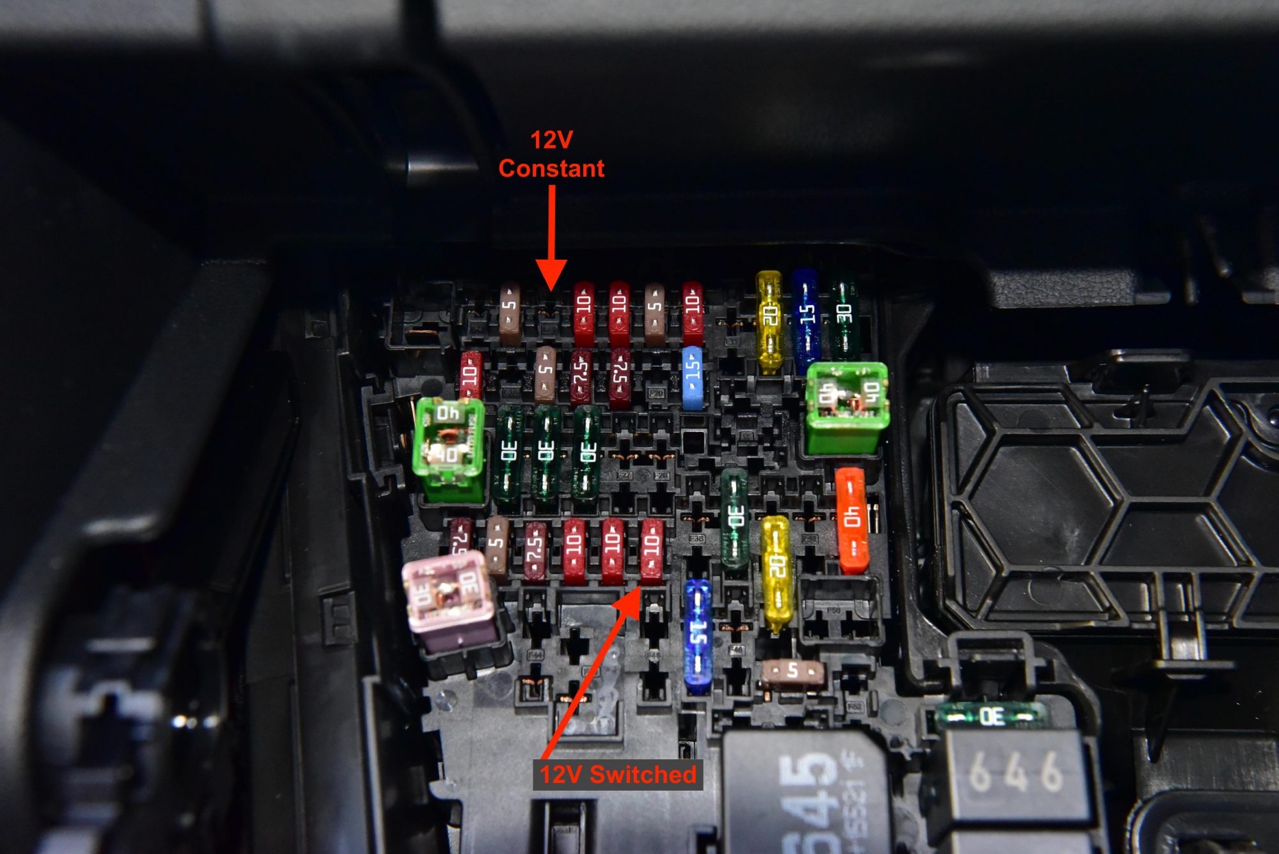
Depends which way around you plug the fuse tap in, the wrong way and the power has to go through the original fuse first, and if there isn't an original fuse then it can't.Got it — I will try it that way first. I thought that the top slot in a fuse tap won't work if the bottom slot was empty, but I guess that's not correct.
Just to confirm, there won't be any issues with different fuse sizes on the ACC fuse tap (10A on bottom, 5A on top), right?
If you have to plug it in the wrong way around due to not fitting the other way then you will have to add an original fuse, but it is better not to do so unless you know what size it should be and that it won't supply power to something that it shouldn't!
The new fuse should always be smaller than the original.
")