lisabon_Q3
Well-Known Member
- Joined
- Mar 20, 2018
- Messages
- 342
- Reaction score
- 271
- Location
- Chelyabinsk
- Country
- Russian Federation
- Dash Cam
- 70mai M500 / X200 / A810, Vantrue N4 Pro, Viofo A139 Pro
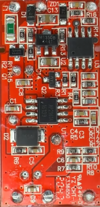
Hi i have UP02 module for a500s-1. I wanna change cut off voltage to 12.1 volt. This board has R17 too. Changing R17 to 9.76k, is it enough? How do we calculate this resistor values? I found the same solution on 4PDA for UP02, he say 470 kohm resistor parallely soldered to R17 and cut-off value is 11,78 volt. On UP02, R13 is "01D" too so i think calculated resistor values is completly different than UP02. I attached image of board. Do u have any idea? Thanks.Ok I figured it out, R13 and R17 are the voltage divider, marked 02D and 01C, 102k/10k ohms, it is read by the microcontroller on pin 4, with 11.8V input, it reads below 1.054V and it switch off the input.
If you want a higher cutoff voltage, you can swap the 102k for a higher value (or add a resistor in series) or swap the 10k for a lower one (alternatively another resistor in parallel)
Edit: did some math, you can get about 12.2V if you put 220k in parallel with the 10k resistor or 180k for 12.4V
Edit 2: if you have 5.6k on hand, you can add it in series with the 102k to get 12.4V and 4.7k in series for 12.3V.
Edit 3: I've decided to order 0603 0.5% SMD resistors to swap out the 10k one, will do the mod for my brother as well.
R17 value
9.42k = ~12.5V
9.53k = ~12.4V (confirmed)
9.65k = ~12.3V (hard to find value)
9.76k = ~12.1V
10k = 11.8V (stock)
On that board the divider is on R17 and R12, so 01C and 103, 10k/100k, what is the default cufoff voltage? 11.4 or 11.6V?Hi i have UP02 module for a500s-1. I wanna change cut off voltage to 12.1 volt. This board has R17 too. Changing R17 to 9.76k, is it enough? How do we calculate this resistor values? I found the same solution on 4PDA for UP02, he say 470 kohm resistor parallely soldered to R17 and cut-off value is 11,78 volt. On UP02, R13 is "01D" too so i think calculated resistor values is completly different than UP02. I attached image of board. Do u have any idea? Thanks.
So the Vanture VP03 works with the 70mai a8100? this has a cutoff of 12V i thought it was 11.6V ?I have the UP03 and 70mai A810. I can confirm there is no selectable voltage anywhere on the unit. It shuts off at 11.8 volts instantly.
I can also confirm that the Viofo hardwire cables would not support parking mode. Very interesting as Viofo USB C cable works fine for a Red Tiger dash cam putting it in and out of parking mode.
The Vantrue VP03 cable works and has a 12Volt shut off switch. confirmed on my bench. Same hardwire cable that is used for N4Pro.
So the vantrue hardwire kit is compatible with the 70mai? if so which model has the highest cut off voltage ?I did some research on the Viofo HK3-C/HK4, as per this post
HK3-H hardware kit arrives! (Viofo is not going to be happy about it)
Thank you for your feedback and input guys! Below I'll try to comment on some of the points: Thanks for heads-up! I was planning on setting it to 60 seconds but this will be an easy programming fix if I need to make the delay longer or shorter for any reason. Actually planning on having own...dashcamtalk.com
Viofo/Red Tiger use pin CC (A5/B5) to carry the 5V ACC signal whereas 70mai/Vantrue uses SBU (A8/B8) pin
Also, it seems like the Viofo HK is a little janky, from my reading, it appears to use a cheaper n-ch mosfet to switch off the output GND and disable the DC-DC converter, and you can have weird voltage 9V on the VCC and 6V on the ACC output lines, I would be wary of plugging it in another brand dashcam in case the dashcam.is being grounded elsewhere, it could fry it.
See the comments in this video
Are you sure that in UP02 divider is on R17 and R12? And 01C and 103 is 10k/100k? Is not the same 01C=103=10k?On that board the divider is on R17 and R12, so 01C and 103, 10k/100k, what is the default cufoff voltage? 11.4 or 11.6V?
You need to figure out the stock voltage divider output then you can change the resistors to obtain the desired input voltage
You can play with this calculator
Voltage Divider Calculator
Try our easy to use Voltage Divider Calculator. Enter any three known values and press Calculate to solve for the other.ohmslawcalculator.com
Assuming 11.6V stock, resulting output voltage of 1.0545V, you need 210k in parallel to 100k (R12 not R17) to get 10k/68k for 12.1V input
Hi, the protection voltage in UP03 is 11.6 Volts.
Wrote the original post before the A810 arrived. Do see in the manual where the cutoff voltage is 11.8V.
Are you guys sure its 11.8V? The manual I found online says 11.6V.I have the UP03 and 70mai A810. I can confirm there is no selectable voltage anywhere on the unit. It shuts off at 11.8 volts instantly.
Yes. This is an old manual, indeed the threshold used to be 11.6 volts. It is now 11.8 V.Are you guys sure its 11.8V? The manual I found online says 11.6V.
Alright, thanks. Also, I was reading your post on modding the kit and I think I found an error:11.8, 3-5A is plently, this thing draw less than 2A
Using that voltage divider calculator after calculating parallel resistance gives a voltage of 12.293 with the 220k. 12.4V for 180k seems to be correct.Edit: did some math, you can get about 12.2V if you put 220k in parallel with the 10k resistor or 180k for 12.4V
| Thread starter | Similar threads | Forum | Replies | Date |
|---|---|---|---|---|
|
|
Hardwire just for regular car-onfunctions? | A810 | 8 | |
|
|
A810 4G Launch | A810 | 8 | |
| G | A810 bricked during installation? | A810 | 5 | |
| Q | Does A800 CPL Filter works on A810? | A810 | 8 | |
| T | Compatible hardwire Kits | A810 | 2 |