Is there really a difference between VIOFO's own HW kit & some no-name Amazon kit?

The cc lines may have resistor in the plugs at each end so this will affect the way the cable is read.
Some USB cables have circuits in them inside the connector housing which i find amazing.
The usb standards i tried to get ages ago but they want your left nut before they give you details.

To help sort what is a fair and reasonable question, i believe the dashcam manufactures would benefit from making this information easily available.

I've built cable testers and it can become a rabbit hole especially when there are electronics within the cable.
 
Here are some examples of the cable tester results.
I don't know what the cable is perhaps the plugs will help identify it.

I need to work on my labeling and filing system lol.
IMG_3667.webp
 
I don't know what the cable is perhaps the plugs will help identify it.
That looks just like the Type-C to Type-C cable included with the 70mai Dash Cam Battery Pack.
Are you testing one of those?
If so, can you see if it supports parking mode?
I need to work on my labeling and filing system lol.
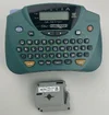
Yes, whenever I get a new product to test, the first thing I do is fire up my Brother PT-65, and label all the parts & accessories.
 

Attachments

  • Brother PT-65 .webp
    Brother PT-65 .webp
    120.2 KB · Views: 41
@Mio NoVue
@Tschingis
@Karagandinez
@LateralNW
Bad News: The $10 Type-C cable tester was DOA / defective.
Good News: I just received the $16 Treedix TRX5-0575.
Good News: I figured out how to identify ACC / ignition PIN in HK6 Type-C connector using Treedix TRX5-0575.
Bad News: I need two more additional HK6’s.
 
Something is not adding up.

1. @EricSan determined that the Viofo HK6 Hardwire Kit uses TWO USB-C connector pins (A5/CC1 and B5CC2) to toggle parking mode. Are these pins operating as a differential pair or are both pins at the same logic level when switching?
2. rcg530 shows the HK6 Molex Connector on the +5V (camera side) with 4 pins but the BP100 only has 3 pins.
3. VIOFO-Support has told us "The fourth pin on the Molex connector (white cable) is for serial port transmission, which can be used to transmit battery voltage to the machines that don't have Bluetooth."

The statement from Viofo implies only three wires are needed for camera operation, which makes sense: Power, Ground and Parking Mode. The fourth wire in HK6 has an additional function for another other purpose.

So why are two wires dedicated for parking mode but only three wires (in total) are used in the Molex connector?


Here is what I have found so far:
Vantrue VP03(II) and VP05(II) Hardwire Kits: use A8/SBU1 and B8/SBU2 to toggle parking mode on an off. It appears that the parking mode trigger with the E360 requires the unit to be powered by the GPS/windshield mount in order for parking mode to work otherwise the camera thinks it is mounted on the battery stick.
Viofo HK3-C, HK4, and HK6 Hardwire Kits: use A5/CC1 and B5/CC2 to toggle parking mode on an off.


@VIOFO-Support
Can the BP100's Hardwire Output Cable (Type-C) (4M) Module be swapped for the HK6 Module?
I am ONLY referring to the module with two connectors than can be removed from the cable, the original BP100 cable would remain installed.
I am having the BP100's cable professionally installed but want to know if I can easily swap out just the module later if I want.


View attachment 89966
The 12V input cable appears to be the same 3-pin plastic Molex connector, same terminal pin size, and the wires are arranged in the same left-to-right order.

The USB output power side has a different size/pin count. The HK6 5V output connector is a 4-pin plastic Molex connector with 4-wires and the BP100 adapter 5V output connector is a 3-pin Molex connector with 3-wires.

1772129219448.webp


@rcg530 Thank you for the response and great photo.
Bummer so that means it's not compatible.
I noticed the 4 vs 3 pin connector discrepancy earlier and asked @viofo what is the function of the 4th pin with no reply.
I wonder why the pins are so much larger on the BP100, hard to imagine it's sized due to current draw.
The fourth pin (white cable) is for serial port transmission, which can be used to transmit battery voltage to the machines that don't have Bluetooth.
 
Last edited:
1. @EricSan determined that the Viofo HK6 Hardwire Kit uses TWO USB-C connector pins (A5/CC1 and B5CC2) to toggle parking mode. Are these pins operating as a differential pair or are both pins at the same logic level when switching?
USB-C Pinout.webp
 
Something is not adding up.

1. @EricSan determined that the Viofo HK6 Hardwire Kit uses TWO USB-C connector pins (A5/CC1 and B5CC2) to toggle parking mode. Are these pins operating as a differential pair or are both pins at the same logic level when switching?

I think you might be misinterpreting what I wrote.

Using the graphic that @Karagandinez posted just above, the CC1 and CC2 pins are virtually identical and merely take into account the orientation of the USB-C plug because it is reversible (unlike USB-A connectors). I am guessing that in any typical USB-C cable, there are a maximum of 10 actual wires: A1 through A11 (A9 repeats A4 for voltage and A12 repeats A1 for ground). On the "other side" of the connector, we have the very same pins that are likely jumpered at the cable connection: B1 through B11 (B9 repeats B4, B12 repeats B1).

With most "typical" USB-C cables, there are only 5 or 6 wires at most, many of the connections shown above are not used in the vast majority of commercial cable offerings.
 
The statement from Viofo implies only three wires are needed for camera operation, which makes sense: Power, Ground and Parking Mode. The fourth wire in HK6 has an additional function for another other purpose.
Oops, I can't insert another quote with the "edit" function for my post...

This is correct:

1) V+ is carried on A4/A9 (B4/B9 for reverse orientation)
2) GND is carried on A1/A12 (B1/B12 for reverse orientation)
3) Parking trigger is carried on A5/B5

The 4th connector on the HK6 carries battery voltage information, but I'm not sure how this information is actually encoded - it is not a simple DC voltage signal, my scope reveals this signal to have some AC component.
 
Last edited:
I think you might be misinterpreting what I wrote.

Using the graphic that @Karagandinez posted just above, the CC1 and CC2 pins are virtually identical and merely take into account the orientation of the USB-C plug because it is reversible (unlike USB-A connectors). I am guessing that in any typical USB-C cable, there are a maximum of 10 actual wires: A1 through A11 (A9 repeats A4 for voltage and A12 repeats A1 for ground). On the "other side" of the connector, we have the very same pins that are likely jumpered at the cable connection: B1 through B11 (B9 repeats B4, B12 repeats B1).

With most "typical" USB-C cables, there are only 5 or 6 wires at most, many of the connections shown above are not used in the vast majority of commercial cable offerings.
This makes sense, thanks for the clarification. CC1 and CC2 are really the same signal, so that when you reverse the connector they electrically remain the same.
I think what confused me was the signal name changed. Normally when I see a different signal name I think it's electrically different.
 
That looks just like the Type-C to Type-C cable included with the 70mai Dash Cam Battery Pack.

I think the cable is from the up04 hardwire kit. I remember that the lead has a different type of coating on it and it's a little stiffer than normal usb cables.
 
Back
Top