You are using an out of date browser. It may not display this or other websites correctly.
You should upgrade or use an alternative browser.
You should upgrade or use an alternative browser.
LFP (LiFePo4) Battery for Parking, 192Wh (DIY)
- Thread starter GPak
- Start date
EricSan
Well-Known Member
- Joined
- Dec 28, 2023
- Messages
- 1,408
- Reaction score
- 1,065
- Location
- Central PA
- Country
- United States
- Dash Cam
- There are ALWAYS user serviceable parts inside!
Careful with a heat gun! They run at 600-1200F and this temp greatly exceeds the working temp of EVERY component on that board. You’ll fry everything…
98nchen
New Member
After blasting the buck boost converter for 5 minutes, I got the temperature up to 80C (measured with a laser thermometer and a thermocouple). I still measure about .2V from the fan pins. I did it 2x, letting it cool back down to ~50C inbetween. I had a fan connected on the 2nd time around. The fan did not spin the entire time I was heating it. I think its a safer option to have it run all the time when its charging from the car
OP
OP
GPak
Well-Known Member
Yes, for some reason the fan is not operational, may be we are missing something, may be it requires external functions to be connected, I am not sure.After blasting the buck boost converter for 5 minutes, I got the temperature up to 80C (measured with a laser thermometer and a thermocouple). I still measure about .2V from the fan pins. I did it 2x, letting it cool back down to ~50C inbetween. I had a fan connected on the 2nd time around. The fan did not spin the entire time I was heating it. I think its a safer option to have it run all the time when its charging from the car
I see you are running 12.1A, so connecting fan to charger's output terminals is a good idea.
If you have not bought the BMS yet, consider the alternate BMS from the parts list.
Also, recently we have discovered that the charger does not have a back-flow protection, therefore please use anti-backflow diode right after the charger's output terminals (please check the LTO thread).
Here are couple of anti-back-flow examples:
https://www.amazon.com/gp/B0BM4QMJ9V
https://www.amazon.com/gp/B0CZ12HBDR
15A version is probably to close to your 12.1A operational current and 50A version is probably overkill, 25A±5A would be Ideal, but I did not see it on Amazon, only on ali-express.
Last edited:
98nchen
New Member
So I've already bought the batteries (DIY'd it). I also bought some schottky diodes (45v 15A) already. Is that ok? or do i need those boards?Yes, for some reason the fan is not operational, may be we are missing something, may be it requires external functions to be connected, I am not sure.
I see you are running 12.1A, so connecting fan to charger's output terminals is a good idea.
If you have not bought the BMS yet, consider the alternate BMS from the parts list.
Also, recently we have discovered that the charger does not have a back-flow protection, therefore please use anti-backflow diode right after the charger's output terminals (please check the LTO thread).
Here are couple of anti-back-flow examples:
https://www.amazon.com/gp/B0BM4QMJ9V
https://www.amazon.com/gp/B0BM4QMJ9V
15A version is probably to close to your 12.1A operational current and 50A version is probably overkill, 25A±5A would be Ideal, but I did not see it on Amazon, only on ali-express.
OP
OP
GPak
Well-Known Member
A schottky diode will work, but it is less efficient and has a higher voltage drop than the "ideal diode".
In any case, with a working current of 12.1A, I would not use diodes rated at less than 20A.
In any case, with a working current of 12.1A, I would not use diodes rated at less than 20A.
98nchen
New Member
u right, I tested the diode with the charger outputting 8 amps, and i appear to lose about 3 amps of current. The diode also gets obscenely hot (66C in about 10 minutes) so im definitely not going to use that. I ordered one of these. It has terminals, so it should make assembly easierA schottky diode will work, but it is less efficient and has a higher voltage drop than the "ideal diode".
In any case, with a working current of 12.1A, I would not use diodes rated at less than 20A.
OP
OP
GPak
Well-Known Member
I ordered the same diode as well and also this one:
I already have 3 others, need to find time to test and compare which one is the most efficient.
In my case with charging up to 8A, the 15A diodes will do, but I may still use a more powerful one, just in case I decide to use faster charging in the future.
I edited my post #19 to replace the schematic with one that shows the anti-flowback diode.
EricSan
Well-Known Member
- Joined
- Dec 28, 2023
- Messages
- 1,408
- Reaction score
- 1,065
- Location
- Central PA
- Country
- United States
- Dash Cam
- There are ALWAYS user serviceable parts inside!
Here is another anti-back flow diode that I found a few days ago. It's rated to 50A, though I suspect it may not actually handle that much current. The current rating does impart some confidence that it would function well with currents up to 15A-20A without encountering much difficulty. I like the ability to order it without the binding posts so I can so lder my wires directly to the board, keep everything low profile, and wrap it in some heat shrink.
https://www.aliexpress.us/item/3256803401816483.html
I like the one you linked better. I looks like the higher current version uses parallel devices to spread the current load, which might increase its longevity. I might pick up the one you linked when I order some extra time delay relays (as backups in case of failure.
OP
OP
GPak
Well-Known Member
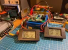
I currently have 4 different anti-reverse "ideal diodes" including the one linked above.
The Red one rated at 15A, shown wired as tested, and the other 3 are shown from left to right on the bottom of image:
15A Grin, 20A Grin (small square) and 50A Black.
Here are the test results for the 15A Red Diode:
Ambient temperature 25°C
Test duration about 30 min, Constant Current, Voltage and Power were gradually growing as battery was charging.
When charging at 8A charging:
The Current drop negligible, about 0.01A
The voltage drop is about 0.14V
The power consumption is 0.14V x 8A = 1.12W
The Diode temperature gradually increased from 25°C ambient to 38°C and stabilized there
The Charger temperature (Inductor) stabilized at 56°C
When charging at 10A charging:
The Current drop negligible about 0.01A
The voltage drop is about 0.17V
The power consumption is 0.17V x 10A = 1.70W
The temperature gradually increased and stabilized at 45°C
The Charger temperature (Inductor) stabilized at 65°C
The Diode average efficiency is about 98.7%
There were no temperature, voltage or current spikes, nothing unexpected.
I tested including from a completely discharged battery at about 9V and at mid-point charge about 12V
I will test and post the results for the rest of the Diodes for comparison.
OP
OP
GPak
Well-Known Member
Do not buy/use the 15A rated long Grin Diode with black heatsink, I am not sure what is it, but it is not an Ideal Diode.
With the 8A charging, the voltage drop is about 0.72V and the temperature reached 85°C in about 3 minutes, after which I stopped the test.
In all fairness, looking at the Amazon description now, it never claimed to be an Ideal diode.
With the 8A charging, the voltage drop is about 0.72V and the temperature reached 85°C in about 3 minutes, after which I stopped the test.
In all fairness, looking at the Amazon description now, it never claimed to be an Ideal diode.
OP
OP
GPak
Well-Known Member
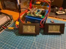
Update on 15A Red Diode,
I wired it as all other Diodes, bypassing the negative power wire and using negative thin wire/jumper to connect to Diode's negative terminal.
The Diode perform exactly the same as previously with one exception, at 10A charging the temperature was about 42°C or about 3°C cooler.
I wired it as all other Diodes, bypassing the negative power wire and using negative thin wire/jumper to connect to Diode's negative terminal.
The Diode perform exactly the same as previously with one exception, at 10A charging the temperature was about 42°C or about 3°C cooler.
OP
OP
GPak
Well-Known Member
Re-post from the LTO battery thread:u right, I tested the diode with the charger outputting 8 amps, and i appear to lose about 3 amps of current. The diode also gets obscenely hot (66C in about 10 minutes) so im definitely not going to use that. I ordered one of these. It has terminals, so it should make assembly easier
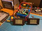
Here are the test results for the Black 50A Ideal Diode, the one you ordered:
The same test condition as for the 15A red diode.
When charging at 8A:
The Current drop negligible
The voltage drop is about 0.13V
The power consumption is 0.13V x 8A = 1.04W
The Diode temperature gradually increased from 25°C ambient and reached 32°C and
When charging at 10A:
The Current drop negligible
The voltage drop is about 0.16V
The power consumption is 0.16V x 10A = 1.60W
The temperature gradually increased and reached 36°C
The Diode average efficiency is about 98.9%
There were no temperature, voltage or current spikes, nothing unexpected and no back-flow voltage.
Based on the test, this diode is a good choice.
OP
OP
GPak
Well-Known Member
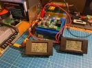
Tested this 25A charger, for about 30 min for each current setting.
https://www.aliexpress.us/item/3256...t_main.22.36121802vsbbBd&gatewayAdapt=glo2usa
With 8A charging - in a 30 min the highest temperature (inductor) reached 42°C (20A version was 56°C), efficiency is about 96.1%
With 10A charging - in a 30 min the highest temperature reached 48°C (20A version was 65°C), efficiency is about 95.4%
With 12A charging - in a 30 min the highest temperature reached 53°C, efficiency is about 94.5%
With 16A charging - in a 30 min the highest temperature reached 69°C (20A version was 105°C), efficiency is about 92.6%
With 20A charging - in only a 15 min the temperature reached about 90°C, and the charger slowly drops the current, I guess some kind of protection, efficiency is about 91%
I think 16A is probably a safe maximum continuous current limit for this charger.
This is about 204W average charging rate for the 4S LFP battery and about 220W average charging rate for the 6S LTO battery.
Attachments
viciouslancer
Member
- Joined
- Sep 23, 2015
- Messages
- 53
- Reaction score
- 17
- Country
- Canada
Would this be better than an EcoFlow River 3? How would either handle a cold Winter climate (Toronto, Ontario, Canada)? I suppose it can charge when warmed up a little (through usage or car cabin heat), it wouldn't be charging when car is off anyway, right?
I do like the LTO route, but it is much more costly than this (or the LFP EcoFlow at 245Wh for CAD$210)
I do like the LTO route, but it is much more costly than this (or the LFP EcoFlow at 245Wh for CAD$210)
OP
OP
GPak
Well-Known Member
The only battery chemistry that can be charged in sub-zero C° temperatures is LTO.Would this be better than an EcoFlow River 3? How would either handle a cold Winter climate (Toronto, Ontario, Canada)? I suppose it can charge when warmed up a little (through usage or car cabin heat), it wouldn't be charging when car is off anyway, right?
I do like the LTO route, but it is much more costly than this (or the LFP EcoFlow at 245Wh for CAD$210)
All LFP batteries should have protection that will not allow charging in sub-zero temperatures, and all of them should auto resume charging between about 0° to +3°C.
And yes, the battery must be connected properly so that it does not charge when the car is off.
The Ecoflow River3 or River2 are the most cost effective LFP options available (double the capacity at half the price of a dedicated battery).
While I am re-configuring my LTO batteries, I have been driving with the River2 for almost two months now, powering two Viofo Mini2 dash cams (5V system), and have had no issues, it works great, and I love the app.
The DIY LFP battery has similar usable capacity to the R2/R3, but is smaller.
It has bypass power to the dash cam, it is very customizable, and may provide faster charge rate.
Finally, since I built it, I can service and repair it myself.
The bottom line is that both the Ecoflow R2/R3 and the DIY LFP/LTO are far better than any dedicated battery on the market.
My recommendation would be:
If you are a DIYer, go for the LTO, especially for cold climates, yes, it is a bit more expensive, but it will last much longer compare to LFP.
Otherwise, the Ecoflow R3 or R2 is a great option.
I believe the River 3 can be configured and remembers to always have the 12V output on when power station is on.
Last edited:
OP
OP
GPak
Well-Known Member
Finally got around to installing the DIY 192Wh LFP battery and a Viofo A329 2ch dashcam in my son's 2023 Dodge Charger 392 Scatpack (wide body).
This car has the starter battery and fuse box conveniently tucked right next to each other in the trunk and there's a nice spot for the dash cam battery right there too.
Very easy installation.
Here is the short video:
This car has the starter battery and fuse box conveniently tucked right next to each other in the trunk and there's a nice spot for the dash cam battery right there too.
Very easy installation.
Here is the short video:
Last edited:
EricSan
Well-Known Member
- Joined
- Dec 28, 2023
- Messages
- 1,408
- Reaction score
- 1,065
- Location
- Central PA
- Country
- United States
- Dash Cam
- There are ALWAYS user serviceable parts inside!
Super convenient to have a nice cubby hole “under” the trunk for the parking battery! That keeps everything clean and neat and I love that the battery and fusebox are both right there, so there is no hassle running wires! What an ideal installation! Nice car! Nearly 500 horses must be fun, too 😉
It took me most of the afternoon to run charging wires through the firewall in my son’s Mustang (had to pull a wheel and the wheel liner to find the pass-through).
Edit: You might want to consider adding a fuse directly after you hit the battery positive terminal, like 2 inches away, rather than inside your DIY battery pack. That way, if any part of your new wiring gets pinched by something moving around in the battery compartment, you blow the fuse right away, rather than having a pinched/exposed live wire still connected to the main battery positive terminal. Just trying to play the long game.
Last edited:
OP
OP
GPak
Well-Known Member
I'm glad you noticed.Super convenient to have a nice cubby hole “under” the trunk for the parking battery! That keeps everything clean and neat and I love that the battery and fusebox are both right there, so there is no hassle running wires! What an ideal installation! Nice car! Nearly 500 horses must be fun, too 😉
It took me most of the afternoon to run charging wires through the firewall in my son’s Mustang (had to pull a wheel and the wheel liner to find the pass-through).
Edit: You might want to consider adding a fuse directly after you hit the battery positive terminal, like 2 inches away, rather than inside your DIY battery pack. That way, if any part of your new wiring gets pinched by something moving around in the battery compartment, you blow the fuse right away, rather than having a pinched/exposed live wire still connected to the main battery positive terminal. Just trying to play the long game.
It is the best practice to install the inline fuse as close to the car's positive battery terminal as possible.
As I mentioned in the video, the original plan was to install the dash cam battery under the seat and power it via a cigarette lighter adapter in the console.
But then we saw a better option in the trunk, so I cut the cigarette lighter plug off the charging cable and used that cable temporarily. (there is still inline fuse in battery pack)
We'll replace the charging cable and install the inline fuse close to the car's battery positive terminal.
Last edited:
98nchen
New Member
so i finally had time to mess with this project. I installed the black ideal diode and found im only seeing a 2V drop across it. maybe im using it wrong? probing the charging circuit, i see 12V lol. my battery is charged to 13.23V