Piggy-back fuseholders - a right way and a wrong way?

I recall from some other part of the Forum that in his case it seemed the piggyback fuse thing was directional.. and by turning it 180 degrees his application worked. Seems strange but worth a try..
 
I recall from some other part of the Forum that in his case it seemed the piggyback fuse thing was directional.. and by turning it 180 degrees his application worked. Seems strange but worth a try..
With thanks I can say that I've tried it both ways. I've tried piggy backing the 12v socket , windows, c
 
It would seem that my fuses are permanent live, but that there's relays or something that turn things off with the ignition. I ended up taking a spur from the rear of the original 12v socket which has worked.
 
Found this thread on google, I have an after market head unit that seems to be draining my battery, taking the fuse out (02 on the left in the picture below) stops the drain so I have to do this every day so I don't wake up to a dead battery.

20150310_215249.jpg


I was thinking of installing a switch, running it around the back and out to the drivers side so I can just switch it off as I get out, what would the best way to do this be?

EDIT: The picture I previously added wasn't the final set up so I can see why I was confused now.
 
Last edited:
double check your wiring of the aftermarket head unit, sounds like you have the permanent and accessory power wired incorrectly
 
double check your wiring of the aftermarket head unit, sounds like you have the permanent and accessory power wired incorrectly
It seems the OP only has access to fuses that are powered all the time.. which.. is very unusual. There must be a block elsewhere that is powered when key in on or acc position..However if there is none.. then a mechanical switch in the line would work.
He could get fancy by using a normally open relay if.. he could find something that is powered only when the key is on or in acc position.. But.. if he could find that source.. there is where he should be powering his camera from.
There is also a similar thread with apparently the same issue https://dashcamtalk.com/forum/threa...cam-even-when-ignition-off.17873/#post-232455
 
Last edited:
Checked my camera yesterday, as some tool almost crashed in front of me on the motorway and the fuse in the piggy back has blown again!

I'm sure it was working the day before and the only thing I did yesterday, was plug my phone in to charge (uses the cigarette lighter on the same circuit)

Could this be overloading it and blowing the 5a fuse?

Can I use an empty slot in the fuse box?

The downside to the Möbius camera, is it's difficult to check it's working in the daylight
 
What size fuse do you have in the bottom slots of the piggy back? What size in the top slots?
 
What size fuse do you have in the bottom slots of the piggy back? What size in the top slots?
From memory, the main fuse is a 20a which was in the fuse box for the bmw cigarette lighter, the extra fuse is a 5a one for the extra cigarette lighter that I installed, which powers the camera
 
Ok, and you are sure the 5A is in the top slot? And the only thing powered by that is the camera? And it is the 5A that is blowing?
 
Another bump for an old thread, thanks Google!

Just installed my mobius dashcam, using a piggy back fuse. It worked great for a couple of weeks and today blew the fuse.

I've used an extra cigarette lighter, which I've installed in that glove box, piggy backing off the BMW cigarette light9 fuse. The BMW one is 20amp and I installed a 5amp fuse next to it, which came with the piggy back connection.

Have I put the original 20amp fuse in the correct slot? The original cigarette lighter still works.

aac883612eb6c772b90acb13b7d5e3ef.jpg


If it's correct, what amp fuse should I use for the 2nd one?

Thanks
It's as per this picture, the 5a fuse is just missing in this photo
 
Ok, well if the 5A is the one blowing then you have a problem somewhere between there and the camera, like a wire that is shorting, or there is a problem with the camera. Because a camera will only need no more than 1.5 amps, so if a 5A fuse is blowing there is a problem. That is what fuses are for so you don't have a fire.
 
5A seems a bit high also, 2A should be more than enough but if 5A is blowing then something is definitely wrong. I'd double check the ground and also double nothing in the live line is exposed or touching something.

Could be possible that the add-a-circuit is faulty also, I've had a faulty one before which is why I always test then with a multimeter first now and save finding out after I've installed everything . I'd change that first as it's cheap enough.
 
Having read this topic I am now comfortable with how the add a fuse works in a sense of direction.

The argument over the two ways to insert, I see how both would work and it makes sense, although of course you risk blowing the bottom fuse if the appliance plus the camera Amp is greater than the fuse.

I assume most people are installing so that the voltage runs up leg A as detailed before? I.e the leg furthest from the wire output?

I think most people.. orient the "add a fuse" with the pigtail pointing in the direction that makes most sense to their wiring plan. It.. is oriented the right way if the pigtail has power with only the top fuse installed.. if it takes both fuses it is the wrong way around but for all practical purposes still perfectly acceptable as the power demands of a camera are exceedingly small.
 
I'm about to hardwire in another dashcam using a piggy-back mini-fuse holder. Prior to doing this, I had a quick ferret at it with a multimeter and reckon ideally the piggy-back should be fitted one war around and not the other. It will work both ways, but one way will result in the current flowing to the dashcam flowing through both fuses in series.

How? Well, check out the illustration:

images


Let's say the left contact in the picture is A and the right contact is B. A is connected to the two sockets above it. B is connected only to the lower socket above it. The red wire is connected to the higher socket above B.

So, I say contact A should be inserted into the battery-side of the fuse socket, rather than the load-side of the socket. Why? Because if B is inserted into the battery-side of the fuse original socket, then the dashcam current has to flow through both piggy-backed fuses in series. This could overload the lower fuse, which has to now handle the current for its original load plus the dashcam.

Does this matter? Probably not, if your dashcam fuse is smaller than the original fuse it was piggy-backed off (so you're getting the intended protection) AND if the total load on the circuit is low, so doesn't blow the lower fuse. But I intend to try and fit it the 'right' way around - space permitting.

Or, maybe I'm completely wrong! Don't think so though. And I've seen comments on Amazon from people moaning about blown fuses in piggyback installations!

Eugene

PS. If I'm right, they really should provide installation instructions.
Hi I have only just joined it was with some amusement I read your question. The answer is really simple, I understand that not everyone is not trained in electrical work, the easy way is to look for an empty fuse location I have yet to see a car without one. First take out the fuse in the Piggyback then put it into the spare slot in the fusebox, Then test the red cable on the piggyback if is live it is fitted the wrong way if it has no power it is fitted correctly. To confirm this put in a fuse and the red wire should become live. The main thing to remember is the fuse is designed as the weak link in a circuit secondly only use fuses of the same size in a piggyback if there is a short circuit both fuses may blow. Personally I would only add one circuit to one piggyback also do not forget to note the changes in the handbook.
 
Hi I have only just joined it was with some amusement I read your question. The answer is really simple
Not quite so simple perhaps..........
I understand that not everyone is not trained in electrical work, the easy way is to look for an empty fuse location I have yet to see a car without one. First take out the fuse in the Piggyback then put it into the spare slot in the fusebox,
It's not necessary to use an empty location.
Then test the red cable on the piggyback if is live it is fitted the wrong way if it has no power it is fitted correctly. To confirm this put in a fuse and the red wire should become live.
With no fuse in either position there can be no power to the red lead.
only use fuses of the same size in a piggyback
Not necessary. It's perfectly acceptable to mix fuse types so long as the fuse box is able to take the current, AND if the piggyback is fitted the correct way round.
if there is a short circuit both fuses may blow.
That's the point of Eugenel's previous correct post. If the piggy back is fitted incorrectly the piggy back circuit current flows through both fuses which is the wrong way to do it.
 
I reckon you plan to have it the wrong way around!

If you connect it as you plan and have both fuses the same rating as the original then you can draw twice the original power, however the cable providing the power to the A side of the fuse will probably only be rated to match the original fuse, or in my case the relay supplying power to the A side of the fuse is only rated to match the original fuse.

If you connect it the other way around and keep the original fuse in the bottom slot then the cable/relay providing the power is still correctly protected from overload.

Realistically, if you are only powering a dashcam and fit a 2 or 3 amp fuse in the top and the original 10 or 20 amp fuse in the bottom then there isn't much to worry about whichever way around you have it.

Apologies for resurrecting this again.
TBH I am very glad I saw this post, as I would never have even thought about it!
Maybe I am missing something major here ... but I am really surprised we have conficting views on this.

I think Nigel is totally correct and the other way is both wrong and potentially dangerous.

Just so I definitely get this right.
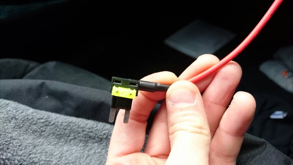
I think this diagram is the wrong way around.
38F69E03-5074-4DC8-8CD2-941974E6350D.jpeg

Facing this way around, Yes both circuits are protected by the desired fuse rating
BUT the supply cable for this fuse socket now has to carry “unfused” the load of both circuits .

IMO the “Hot” or +12V, or powered side of the fuse box should go to the blade on the side of the pig tail.
Fitting it this way means all the power has to go through the original manufacturers fuse (in my case 15A for the cigar lighter) . I intend to put a 7.5A fuse in the top holder ( i.e. protecting my double USB power outlets front and back).
In the event the next owner unwittingly used 7.5A on my new circuit and 15A out of the original Cigar Lighter socket.
As soon as his devices pulled more than 15A; then the original fuse would blow. IMO as it should do as Mercedes only designed the supply cables to take 15A, not 22.5A. (TBH I would hope that Mercedes Margin for error would easily accomodate that, .... but lets face we are after all connecting cheap chinese tat! )

OK thats my view but have I got it right?
Namely that the powered/hot side of the fusebox socket must go to the side of the Piggy back with the pigtail?


Postscript:
1. As I am not a trained auto electrician, I rarely mess with car electrics, but if I do; I want to make sure its done to a professional std. - note after picking up a new SL500 with a custom 1000w amp fitted, I was ignominiously pulled over by the Police on the Motorway! “Excuse me sir I think your car is on fire!” Opened the boot and a gush of smoke enveloped us. Apparrently the technician had done something wrong, and it was seconds away from bursting into flames ... it cost Mercedes > £3,000 to rectify. ( all new boot liners, parts of the hood covering etc.) a real leveller!
2. Sure in the real world, just fitting a dashcam with such a low current draw, I agree probably would never matter.
3. So why the hell am I bothering? Bluntly er ... public liability!.
If say I fit a double USB front and back. And the next owner decides to connect some of these new USB C devices .. and use the original Cigar lighter (in my case) all at the same time. This could potentially induce a huge current overload.
4. Looking with a dentists mirror underneath this fuse block thingy, there seem to be wires of all different sizes coming out of it. So there is a possibility the feed for different fuses could be “sized” for each circuit i.e. not capable of supplying a given increase.
 
Yes the fuse is meant to protect the whole circuit including the input to the fuse box. If you wire it your way you're basically sharing the load of the existing fuse. If you wire it the other way, so power comes from the input side of the existing fuse, you're adding more potential load than what the wires are made to handle.

For a dash cam either way is probably fine but IMO better safe than sorry. Plus if there is some kind of short, you can easily draw much more power than the 1 or 2 amps of the dashcam, and that becomes dangerous
 
Thread starter Similar threads Forum Replies Date
I Dash Cam Discussion 0
F Dash Cam Discussion 7
quazi Dash Cam Discussion 6
Back
Top