Piggy-back fuseholders - a right way and a wrong way?

Yes it is....
No it is not!

Apparently it is like that in some cars, but certainly not in mine.

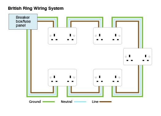
I would make a comparison with plugging in my desk lamp into a wall socket in my house, however since my house is a UK house it is different to yours, we have a bus (ring circuit) supplying the sockets and a fuse in each plug that we plug into the sockets... Just like cars, things don't always work in the same way!
 
I just want to post that I got some fuse taps from Viofo and someone had asked what was the rating of the fuses provided. Well they are orange and do not show amps. I look on the standard chart online and there is no orange so I have no clue what the rating is.
 
Firstly this is in no way comparable to house wiring beyond having a few common components. Inside a car fusebox there will be at least two power feeds: Always on, and on only when the key is turned on (switched). Some of the newer cars have delayed off circuits which could add other power feeds into the fusebox. In some older cars these feeds are done with wire jumpers, not buss bars, although the functioin is exactly the same. All we need to know about this is that the power feed goes to one side of any given fuse, and the other side of that fuse goes to the load.

To make this easy to understand I'll use "12V" to identify the power feed to the fusebox, whether always on, switched, or delayed. So your interior dome lights go like this:
12V to fuse, other side of that fuse (downstream side) to the door switches, then from there to the dome light. Should an overload or short occur anywhere past the other "downstream" side of this fuse, the fuse will blow to protect the fusebox and other car wiring.

Now let's consider adding onto this. The car was designed so that the wiring in this circuit could sustain normal operation of the dome light at the expected load without the fuse blowing. If we add our new load to the 12V side of the fuse, the original car fuse for that circuit is not protecting the new load, but it stil protects the dome light circuit. If our new load shorts or overloads the circuit, the fusebox and car wiring will see that load unprotected and you've got problems.

Now lets add a fuse for our new load so that an overload or short in the new circuit will cause the new fuse to blow before the fusebox and car wiring are affected. You might think you're protected but you're not, because we haven't accounted for the extra power being used by the new load during normal operation. When that is added to the power used by dome light operation, you might be overloading the 12V power feed at the fusebox which was not designed to have this extra power drawn from it. Being that our new load is a dashcam which uses little power, there is probably enough capacity for it's new load but we cannot know this for certain. We have now increased the total load.

So let's change the new load to the other "downstream" side of the dome light fusewithout adding a new fuse for it. Now if the new load shorts or overloads, it has only the dome light fuse to protect the fusebox and car wiring, and the dome light fuse will protect these adequately, but it will not protect the new load wiring and load that is not designed to handle as much power as the dome light normally uses and is fused for. During normal operation the total load is the same as before. It is only when the new load malfunctions that we have a problem.

Now let's add a fuse to our new load which is now drawing power fron the "downstream" side of the larger dome light fuse. Again the total load remains the same during normal operation, but that total load my now be more than the car fuse can tolerate, thus it might blow without any malfunctions occuring. Normally the car fuse and wiring will have some extra capacity designed in so that increased resistance over time due to wire and connector aging will be handled while still covering a larger overload. If a short or overload occurs in the dome light circuit, the dome light fuse will blow and now our new load has lost it's power source, but the fusebox and car wiring go unharmed so we don't have a problem other than the loss of function of our new load (dashcam). Now instead of a malfunction in the dome light, lets consider it working normally and having an overload or short occur in our new load, whose fuse is smaller in capacity than the dome light fuse feeding it. This will blow the smaller fuse of the new load before affecting the dome light fuse, the fusebox, or the car wiring. The only problem we have is loss of function of the new load (dashcam) and the dome light will still function normally.

Now lets consider that everything is functioning normally in both the dome light circuit and with the new load, both of which are fused appropriately as shown above. Can we possibly have a problem? Yes, and here's why- we have increased the normal load into a higher total load which the 12V at the fusebox must supply. If it cannot supply the total power safely, then we can have a problem even with no fuses blowing and with everything functioning normally. Since we cannot know for certain whether the 12V at the fusebox can tolerate the added load there is still some risk, but being that our new load is a dashcam using very little power, this risk is very minimal. In engineering electrical circuits, thr normal practice is to size the wire to meet the expected load, then fuse at a level which will carry the expected load, but with a small safety margin built in because when the wiring and the fuse are the same rating it is impossible to be certain that the fuse will blow before the wiring gets harmed. So the wiring feeding any fuse in a car will be able to carry more power than the fuse does, even if only slightly. Since our power needs for a dashcam is also slight it's very unlikely that our new total load will exceed the ability of the car wiring to handle it safely. If we fuse things like I last described here, each circuit we're playing with will be protected with the lowest possibility of one malfunction causing another malfunction.

So as I posted before, the safest way to do this has this power flow: 12V > domelight (or other) car fuse > dashcam fuse > dashcam.
It is not the only way, and as I've shown above the car can be protected doing this differently, but this is the best way for the reasons already noted. Being that our power requirements are so small, I would not worry if we cannot determine which side of a car fuse is 12V and which side is downstream, since our smaller cam fuse will blow if it has a problem which protects the car anyway and that is our main goal.

Just remember that I've shown where even normal operation could possibly cause the car fuse to overload and blow, which is why you never want to tap into any fuse which could affect safe car functioning such as exterior lighting, engine controls, or airbags. This is the most important part of doing a dashcam install safely so never break this rule even if no other suitable power source can be found. Better to be safe without your cam than to risk death or injury just to have it.

Whew, I feel like I've just written a term paper for college but I hope that everyone can now understand what we're dealing with and how to best do it safely with the least risks in everything.
Phil
 
No it is not!

Apparently it is like that in some cars, but certainly not in mine.

I would make a comparison with plugging in my desk lamp into a wall socket in my house, however since my house is a UK house it is different to yours, we have a bus (ring circuit) supplying the sockets and a fuse in each plug that we plug into the sockets... Just like cars, things don't always work in the same way!

I would think all some.. including UK homes.. homes have power coming into their home.. first through the meter then going to a distribution panel. Inside that distribution panel..typically there is a main breaker or switch (that can also act as a high capacity fuse) Also inside that panel there will be a row of screw in fuses (old system) or switches (breakers that will trip on excessive load). That switch.. breaker or fuse will be connected inside the panel to the power coming in.. and on the other side to your application.. could be one wire or several.. but each of those wires can go to multiple outlets or uses.. to a light switch.. then on to an outlet or two. Or.. for high load requirements you may have a dedicated breaker / fuse.. as in your electric stove.. hot water heater.. furnace etc. There will also inside that panel be a return buss where the return wire is connected to complete the circuit. And.. a ground to earth as well When the home was wired the design should balance out the expected load so that not all the outlets are on one circuit.

I do think the analogy of using the home wiring system is an apt comparison.. some of the terminology is different and as the whole vehicle is considered to be "grounded" it is only necessary to use one wire to the application.. and then to complete the circuit just ground it to the closest metal.. instead of.. as in a home situation.. have to run a wire all the way back to the panel.
 
Last edited:
@Ralph2
You obviously don't understand how the "Ringed Mains" in the UK function- to say they are weird to the rest of us is an understatement of the highest nature :LOL:

Phil
 
Now let's consider adding onto this. The car was designed so that the wiring in this circuit could sustain normal operation of the dome light at the expected load without the fuse blowing. If we add our new load to the 12V side of the fuse, the original car fuse for that circuit is not protecting the new load, but it stil protects the dome light circuit. If our new load shorts or overloads the circuit, the fusebox and car wiring will see that load unprotected and you've got problems.

Now lets add a fuse for our new load so that an overload or short in the new circuit will cause the new fuse to blow before the fusebox and car wiring are affected. You might think you're protected but you're not, because we haven't accounted for the extra power being used by the new load during normal operation. When that is added to the power used by dome light operation, you might be overloading the 12V power feed at the fusebox which was not designed to have this extra power drawn from it. Being that our new load is a dashcam which uses little power, there is probably enough capacity for it's new load but we cannot know this for certain. We have now increased the total load.


Whew, I feel like I've just written a term paper for college but I hope that everyone can now understand what we're dealing with and how to best do it safely with the least risks in everything.
Phil
Whew indeed. Well written.. but.. using your rational there is no safe way to add an extra load.. no matter what method we use.. taking extra power will require an additional load on the internal buss. True that you are limiting the total flow through that first fuse thus guaranteeing that your total (on that circuit) will not ever exceed the original capacity. But.. in my very unprofessional opinion.. that buss is designed to handle a lot more than a couple of 5 amp circuits. If there are those that intend to draw significant power from the fuse panel.. it would be far better / safer to use relays and source directly from the battery.
 
@Ralph2
You obviously don't understand how the "Ringed Mains" in the UK function- to say they are weird to the rest of us is an understatement of the highest nature :LOL:

Phil
True.. Never have seen a "Ringed Mains" but.. the Google ever helpful.. Makes sense that things are a bit different in the UK... :):) I will edit my previous post:)
 

Attachments

  • 320px-Ring_circuit.svg.png
    320px-Ring_circuit.svg.png
    25.2 KB · Views: 12
@Ralph2
You obviously don't understand how the "Ringed Mains" in the UK function- to say they are weird to the rest of us is an understatement of the highest nature :LOL:

Phil
Our ring main looks like this:

Ring-Loop-Dia.jpg


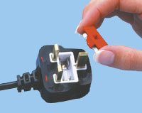
And we have fuses in all our plugs, plus an earth pin that always makes contact before the live can make contact:

uk_fuse.jpg


Not weird at all, it is normal, to us, that is how house wiring works, and we also use twice the voltage you do at 240 volts 50Hz AC.
 
I just want to post that I got some fuse taps from Viofo and someone had asked what was the rating of the fuses provided. Well they are orange and do not show amps. I look on the standard chart online and there is no orange so I have no clue what the rating is.
There are several standards for the fuse colours, so realistically the colour means nothing, which was why I asked.
Thanks for trying to answer.
 
Our ring main looks like this:

Ring-Loop-Dia.jpg


And we have fuses in all our plugs, plus an earth pin that always makes contact before the live can make contact:

uk_fuse.jpg


Not weird at all, it is normal, to us, that is how house wiring works, and we also use twice the voltage you do at 240 volts 50Hz AC.
I know.. it is a safety thing.. at 240 volts a shock can kill.. at 110 most times it just hurts.
 
I know.. it is a safety thing.. at 240 volts a shock can kill.. at 110 most times it just hurts.
It doesn't kill when you have an earth leakage circuit breaker, and with our ring circuits we have dual redundant earth paths to ensure that electric shocks are detected.

And in any case it is far more difficult to get an electric shock from a UK plug and socket than a USA one, eg the live hole in the socket has a shutter over it so that you can't touch it or insert anything until the earth pin is inserted to open the shutter, and the pins on the plug are insulated except for the tips so that even if you touch them as you insert the plug you still don't get electrocuted.
 
I still say weird since only the UK is like this. But weirder does exist, such as the remote areas of Australia and New Zealand which have one wire feeding a string of locations, so the house closest to the trunk line sees higher voltage than the house 5KM further down, and this done with the earth itself- not a second wire- completing the circuit via the ground rod at each house. Wet soil gets you higher voltage while dry soil gets you less. If the house closer to the trunk line turns everything on your power can drop to near-useless levels 5KM away. I understand they're upgrading it all to 2 wires now but some may still remain in use. The US now requires similar 'shuttered' outlets, but ours open when both power-carrying prongs go in; they won't open if only one side is pressed inward. There are advantages and disadvantages to every common home wiring method, with parts (like 50 or 60Hz and 120 or 240V) simply being standards adopted long ago which would cost too much to change now, as that would render every electrical gadget within that system useless afterwards. Ring Mains came about originally as an economy measure only- it takes less wire to do this than to run individual branch circuits like everyone else does, and originally each house had only it's own ground rod for safety. Many older houses were designed around lower expected loads, so that if too much stuff is plugged in with Ring Mains the wiring, being unprotected, can overheat. Ring mains can also overload when the drawn power is closer to one end of the feed than the other (as current takes the shortest path). With the US and similar systems this cannot occur, as the wiring itself is protected on each branch circuit and branches draw power only through one direction. In the US, there are 3 wires into each house, one of which is a ground which ties in to the house ground rod for redundancy. Twist- connecters (wire nuts) are allowed here, but in Germany only screw-connecters are used. I learned this stuff from some old house and construction forums I'm a part of

I'm sure some of us find these things interesting, but we're getting well away from the topic. My point was and is to make it clear that trying to compare a car's wiring system (which is almost universally basically the same world-wide now) with house wiring (which is vastly different everywhere) will lead only to argument and confusion, so perhaps we would do well to abandon that approach. Let's stick to car wiring, OK?

Phil
 
Ring Mains came about originally as an economy measure only- it takes less wire to do this than to run individual branch circuits like everyone else does, and originally each house had only it's own ground rod for safety. Many older houses were designed around lower expected loads, so that if too much stuff is plugged in with Ring Mains the wiring, being unprotected, can overheat. Ring mains can also overload when the drawn power is closer to one end of the feed than the other (as current takes the shortest path). With the US and similar systems this cannot occur, as the wiring itself is protected on each branch circuit and branches draw power only through one direction. In the US, there are 3 wires into each house, one of which is a ground which ties in to the house ground rod for redundancy. Twist- connecters (wire nuts) are allowed here, but in Germany only screw-connecters are used. I learned this stuff from some old house and construction forums I'm a part of
Actually, they were designed at a time when plug in electric heating was expected to become the norm and for there to be a demand for a lot of nearly free nuclear power and many sockets, and so they were designed to be able to carry more power to more sockets than previous systems while having unlimited numbers of sockets and also costing less to install since they need less copper.

They don't overload because the total load is limited by a breaker at the consumer unit protecting the ring, normally 30A, and the cables for individual devices are protected by their own fuse in the plug so that you can use nice thin 1 amp wire for your desk lamp and 13 amp wire for your electric heater and it is all correctly protected by fuses that match it's capacity. Current is shared over both paths around the ring, you do get more flowing from the closer end, but even using the maximum device fuse you will not overload it unless someone puts all the sockets right at one end and then runs a long distance the other way, which never happens, and even then I think the wire would just get excessively hot rather than catch fire.

According to Wikipedia they are used around the world, UAE, Beijing, Indonesia, Uganda... They are not actually a legal requirement in the UK, they are installed because they are considered either the best or the cheapest legal solution.
 
I hope... that this video puts an end to the question on which way to install an add a fuse thingmie.
 
I hope... that this video puts an end to the question on which way to install an add a fuse thingmie.
Sadly it does not. The info that he provides is incorrect. I haven't got the time to explain any further right now though. Sorry, hopefully soon, unless someone else wants to explain the faults. I probably won't get to it today though
 
I hope... that this video puts an end to the question on which way to install an add a fuse thingmie.
Anyone can do a YT video and claim to be correct. Which many aren't.

Phil
 
Anyone can do a YT video and claim to be correct. Which many aren't.
Phil
True.. but this one seemed to have a better explanation on how an "add-a-fuse" thingmie works than the description some have tried to express. As an old saying goes.. a picture is worth a thousand words.. and here we have better yet a video.. Showing the various ways.. and consequences of installing it one way.. or the other.
I appreciate that this video did not address the additional load put on the internal buss which seems to be the sticking point for some.. However the electrical engineers would have designed it to adequately handle the load of ALL the possible upgrades and options available... and with some degree of a safety factor.
No way any engineer factored in that someone would run a fuse tap IMO.
 
No way any engineer factored in that someone would run a fuse tap IMO.
Even if they did, they would base their calculations on someone inserting the fuse tap the safe way around.

... So your interior dome lights go like this:
12V to fuse, other side of that fuse (downstream side) to the door switches, then from there to the dome light.
...
That is not correct, my interior dome light doesn't just switch on and off, it fades off slowly so that you are not suddenly left in the dark. The door switches are not connected to the light at all, they are connected as inputs to the main computer which uses a transistor to switch the dome light and uses PCM to fade it out, means that the light can come on when you turn the engine off so that you can see how to open the door and stay on after you shut the door so that you can see your way into your house. You don't want to overload the transistors on the main computer board! Not even the boot light works like that, the bulb on that is always connected to live power, it is switched on the earth side.

Making assumptions on how electrics work can be dangerous, put the fuse tap in the safe way around and you don't need to worry.
 
Thread starter Similar threads Forum Replies Date
I Dash Cam Discussion 0
F Dash Cam Discussion 7
quazi Dash Cam Discussion 6
Back
Top