I had to pull out my daughters best wrighting sticks for this one...A correct graphic would really be nice at this point.
")
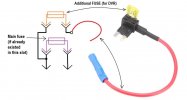
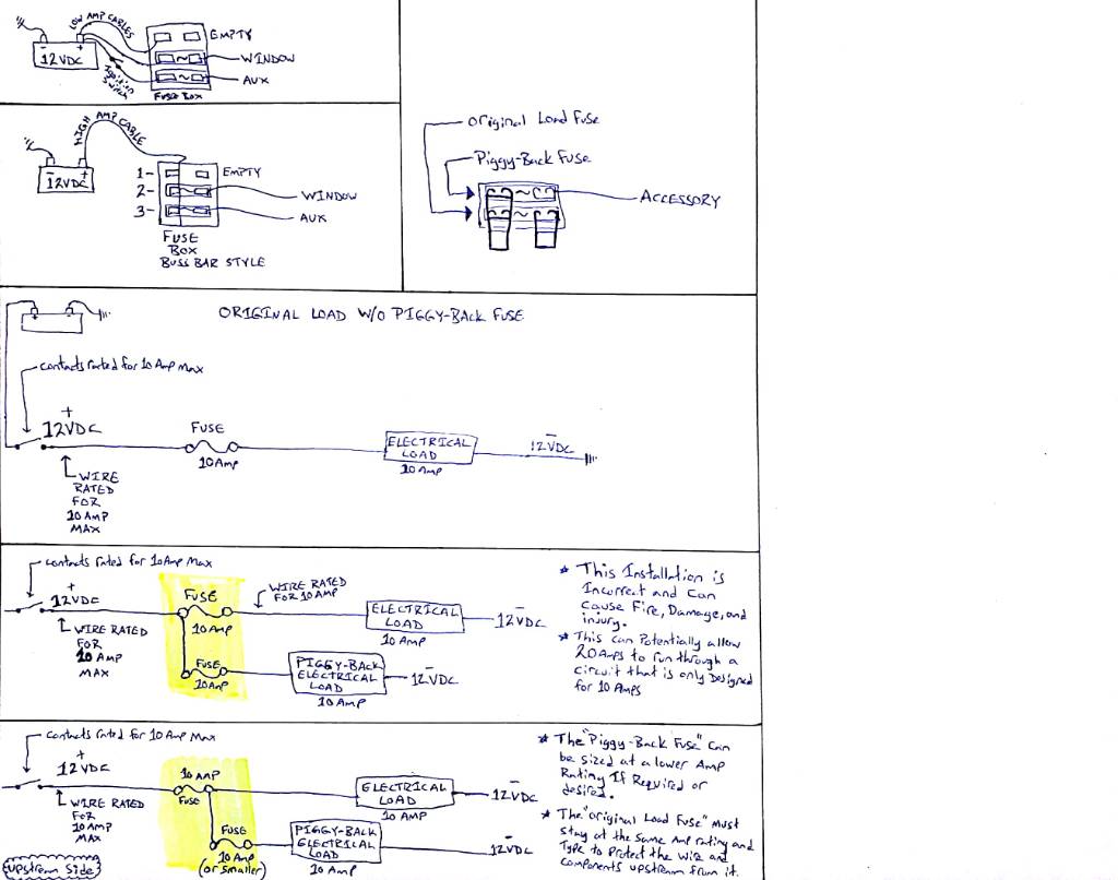
The problem with sending your 12 VDC to the common side of the Piggy back Fuse holder (side A) is that it can overload the circuit that the original Fuse is trying to protect. In my example within the picture you can see that, if installed incorrectly then the Piggy back Fuse holder could allow 20 Amps to enter a 10 amp circuit. You may get it to work after you install it but if something shorts out or fails then you may cause a lot of damage that could have been avoided if you simply ran your Piggy backed circuit in series through the original Fuse. Let's keep in mind that a Fuse is not there to make the equipment operate, it is there to protect the circuit when it fails.
This is where my knowledge is limited, I'm not a car guy, I know voltage setups in buildings and equipment. I've only ever played around with automotive wiring for pleasure so my experience is limited in this area in the sense that I don't know if all manufactures follow the same standards and practices. There is reason that the automotive industry would do things a little differently but a lot of the principles will apply regardless.
Fuses are run in series all the time. This is common in high voltage and low voltage systems, both AC and DC as well. They are designed to pass through their rated capacity and fail once the amperage exceeds the rated amount by a specified amount and or time, dependng on what the Fuse specs include.
Fuses are sized to protect the circuit not the load. If your power window motor winding burns out and shorts to the chassis then this could cause the power wires to light up like a glow stick. The Fuse is sized to protect the wire and components from failure, once the Fuse blows the motor has already failed. If a 10 amp Fuse is installed in a circuit its most likely because that circuit can't handle any more than 10 Amps. The manufacturer doesn't want the motors in rush current to cause the Fuse to open when you use the window so the Fuse won't be sized exactly to the operating current of that device. Instead they will put the biggest possible Fuse into that circuit so that these nuisance trips don't occur and the circuit still remains protected as designed. Increasing the load beyond the fuses rated ampacity is risky, dangerous, and asking for an unexpected failure. Rule of thumb is that this failure won't happen the first time you use it. For instance, keeping with the power window circuit for example, your window motors will draw a modest amperage when you use them in the fall, but when you try to roll down all the windows at the same time to clear the ice off of them in the winter the motors will pull much more amperage as they struggle to break through the ice. The Fuse and circuit need to be sized for this even though it may only happen once a year (depending where you live), for the rest of the year the Fuse would appear to be over sized. If you have bypassed the circuits 10 amp Fuse in order to pull more amperage, then when this time comes for that circuit to require the protection it was supposed to have, you will have melted wires or caused a switch to fail. Instead of simply replacing the Fuse and moving your Piggy back to a different circuit you now have to rewire and trace down everything that got damaged.
Putting the Piggy back Fuse in series with the original Fuse will retain the circuits original intended protection and provide a means for you to create a second circuit to have an equal or lower rated ampacity. If you run wire from the Piggy back Fuse to your dash cam and the wire is only rated for 5 Amps protection then you should NOT be installing a second 10 amp Fuse into the Piggy Back slot but rather the proper 5 amp Fuse should be used. The original 10 amp Fuse should remain in the original circuit slot. This new 5 amp Fuse will have no effect on the original 10 amp Fuse that is still protecting the original circuit.
I suspect when people are saying "the original Fuse size should be used" that there was some lost in translation confusion or misunderstanding as the info was passed along. My suspicion is that people have been installing these on circuits that were already fully loaded and it was causing the Fuse to open (blow) , this could lead to people putting larger fuses in to stop this but that creates a hazard. So the manufactures probably specified something like "must use the original size Fuse" implying that the original size Fuse was to be used to serve the original circuit, but was misunderstood to mean that the original size Fuse must be used in both circuits. As I said above, if the wires or relays that are installed into your new circuit can't handle the full load of the original size Fuse then the correct (smaller) size Fuse should be used.
Its a long post but I think I covered most of the topics that have been discussed...
Sent from my SM-A520W using Tapatalk
")