Proper way to install an Add-A-Fuse?

tsouzee

Member
Joined
Jun 26, 2016
Messages
42
Reaction score
4
Country
United States
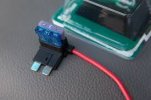
I know there many explanations out there, but I'm still confused. I'm about to hardwire my dashcam. I actually need to tap into two fuses because of parking mode. Anyway, I understand each fuse has the IN and OUT. Meaning one terminal has the power and the other does not. Soooooo, using the attached picture, which way am I supposed to plug the Add-A-Circuit in? Is the left prong of the Add-A-Fuse going into the hot terminal, or the right prong? Thanks.

Also, just want to confirm that the blue fuse in that Add-A-Circuit is thee original fuse that you are tapping into?
 

Attachments

  • images.jpg
    images.jpg
    6.4 KB · Views: 140
The white fuse is dashcam's fuse. And the blue one is car's fuse.
 
Yes it does. So it look like the prong labeled 'from battery' sh ould go into the side of the fuse that is the IN (hot). In other words the side that shows the voltage on the multineter when tested. Thank you very much.
 
Hope this helps :)
This is how the current flows through:
Nice representation.:)
You do mention it but it is important to have the fuse tap oriented the right way. The accessory wire must be on the cold (no power) side of the fuse block. One way the power to your accessory goes directly to the second fuse.. the other way would have the power go thru the original fuse first. It will work either way.. but could overload that first fuse.
Not likely with the current a camera uses but fuse taps are used for larger loads as well and you could have a situation where (by inserting the fuse tap the wrong way) you have, say an original 10 amp fuse and want to draw another 10 amps. The wrong way draws it all through the original fuse.

Harder to explain than to suggest you study the drawing again.
 
Thank you. Confusion has set in again. So which is considered the 'accessory wire' on the add-a-fuse?
 
The right pin:

add_a_circuit_standard_blade_1.jpg
 
Last edited:
Happy to help :)
 
I plugged my add-a-fuses into unused sockets. That way the orientation is forced on you (assuming you only put one fuse into the add-a-fuse.) Plug it in the wrong way and you get no power.

You could use this fact as a way to find correct orientation even when selecting a used socket. Don't put in the accessory fuse at first. If you get power to the camera with only one orientation then that is the correct one.

You can see in this modified image that one way has a simple path for power to reach the camera through the top fuse only, while the other requires power to flow 'backwards' through the bottom fuse, then forwards through the top fuse.

add_a_circuit_standard_blade_x.jpg
 
Last edited:
Not likely with the current a camera uses but fuse taps are used for larger loads as well and you could have a situation where (by inserting the fuse tap the wrong way) you have, say an original 10 amp fuse and want to draw another 10 amps. The wrong way draws it all through the original fuse.
That is what it should do, the original circuit was fitted with a 10 amp fuse to protect the car, if you bypass the original fuse when taking the extra 10 amps then you can double the load on the supply wire over what it was designed for and that is enough to melt the insulation, cause a short and set fire to the car. You should take all the current through the original fuse so that the original fuse can continue to protect the car as it was designed to do. If you bypass the original fuse as you are suggesting then there is not much point having a fuse!

A camera doesn't take enough power for it to matter, but in your example where you are taking 20 amps through a 10 amp supply wire it could cause a serious problem.
 
I was going to put 'correct' in quotes in my previous post but decided to avoid complicating things.

I agree that going through both fuses is safer, but what I learned when installing mine was that the unused fuse sockets in my vehicle only have a metal contact on one side (hot.) If you plug a fuse in there is literally nowhere for current to flow.
So ... how are those sockets wired, and how are they rated for current? It's thought provoking.
I decided they are just wired in banks of similarly functioning sockets (always on, switched,etc). I believe all of the hot pins in each group are simply wired together. Each fuse is not rated to match the wiring to that socket, the fuses are rated to match the equipment they feed.

It's just a theory. But knowing how things tend to be designed, I suspect they aim to keep it simple. They will specify max current for a group of fuses rather than for individual ones. Increasing current through an individual fuse holder will only be a problem if it also takes the group of fuseholders over their allocated current.

P.S. I also discovered that my leased van had one of the standard fuses missing right from new. It meant trip counters weren't working properly. I'm pretty sure it also disabled the traction control. I wondered why I was getting wheelspin so easily during the year I've been driving it! God knows what else it controlled. :eek:
 
Thanks everyone for your help. I installed today. I will write a review on the cam once I can pull initial footage. So did I do it right?!!!!! My hot terminal are on the top of each fuse for reference.IMG_20160923_173448795.jpg
 
Looks correct to me :)
 
I was going to put 'correct' in quotes in my previous post but decided to avoid complicating things.

I agree that going through both fuses is safer, but what I learned when installing mine was that the unused fuse sockets in my vehicle only have a metal contact on one side (hot.) If you plug a fuse in there is literally nowhere for current to flow.
So ... how are those sockets wired, and how are they rated for current? It's thought provoking.
I decided they are just wired in banks of similarly functioning sockets (always on, switched,etc). I believe all of the hot pins in each group are simply wired together. Each fuse is not rated to match the wiring to that socket, the fuses are rated to match the equipment they feed.

It's just a theory. But knowing how things tend to be designed, I suspect they aim to keep it simple. They will specify max current for a group of fuses rather than for individual ones. Increasing current through an individual fuse holder will only be a problem if it also takes the group of fuseholders over their allocated current.
In a house fuse box then certainly you can expect all the fuses in a bank to share a supply, but in my experience each fuse in a car passenger compartment fuse box tends to have it's own supply wire as it is normally not located at the start of that circuit, the fuse rating then matches the cable rating so you do need to take all power through the original fuse to be safe. Adding a camera wont start a fire, but taking an extra 10 amps from a 10 amp fuse as in the example above does risk a fire and unlike home furnishings, automotive carpets/seats/dashboard etc are not flame retardant (unless they are child seats!), car fires are very nasty, especially if you are in the fast lane when it starts.
P.S. I also discovered that my leased van had one of the standard fuses missing right from new. It meant trip counters weren't working properly. I'm pretty sure it also disabled the traction control. I wondered why I was getting wheelspin so easily during the year I've been driving it! God knows what else it controlled. :eek:
Probably the ABS fuse, the trip counters often get their data from the ABS wheel speed sensors and the traction control also uses the same data.

I always test the ABS when I get a new car to drive, after testing an Astra hire car and having the brake pedal hit the floor, even though it felt fine in light use, I no longer do it on a hill!
 
I'm pretty sure that the wires from the harness that connect to the fuse box are of different gauges, the amperage that a particular slot can handle depends on the wire. I'm going to get to the bottom of this on my next visit to the authorised service station.
 
Last edited:
I always test the ABS when I get a new car to drive, after testing an Astra hire car and having the brake pedal hit the floor, even though it felt fine in light use, I no longer do it on a hill!
Since they never gave me an owner's manual, I don't know for sure if it even has ABS! I've never braked hard enough to skid or get any sense of ABS kicking in.
Wheelspin on pulling away is another matter. Front wheel drive sucks.

I may be able to get a mirror or snake cam behind the fuse panel to see what it looks like. I'll try later.

Back on topic, a good approach would be to fit the add-a-fuse the ugly way first (feeding through both fuses.) If it works without blowing a fuse it's all good, and you know you're not exceeding any ratings. If it blows the existing equipment fuse, you may be forced to do it the tidy way (what most consider 'correct.')

Either way you need to consider how critical the system you're tapping into is. For some things having a fuse blow while driving is a greater risk than exceeding a wire's rating by a tiny amount. Losing the radio is fine, you don't want to lose headlights or brake lights. Some sources recommend the brake light fuse. If that blows while driving would you know about it?
 
Back
Top