Hex
Member
- Joined
- Dec 13, 2015
- Messages
- 18
- Reaction score
- 40
- Country
- Germany
- Dash Cam
- SG9665GC
Hi,
welcome to everyones favorite segment: Teardown!
Foreword
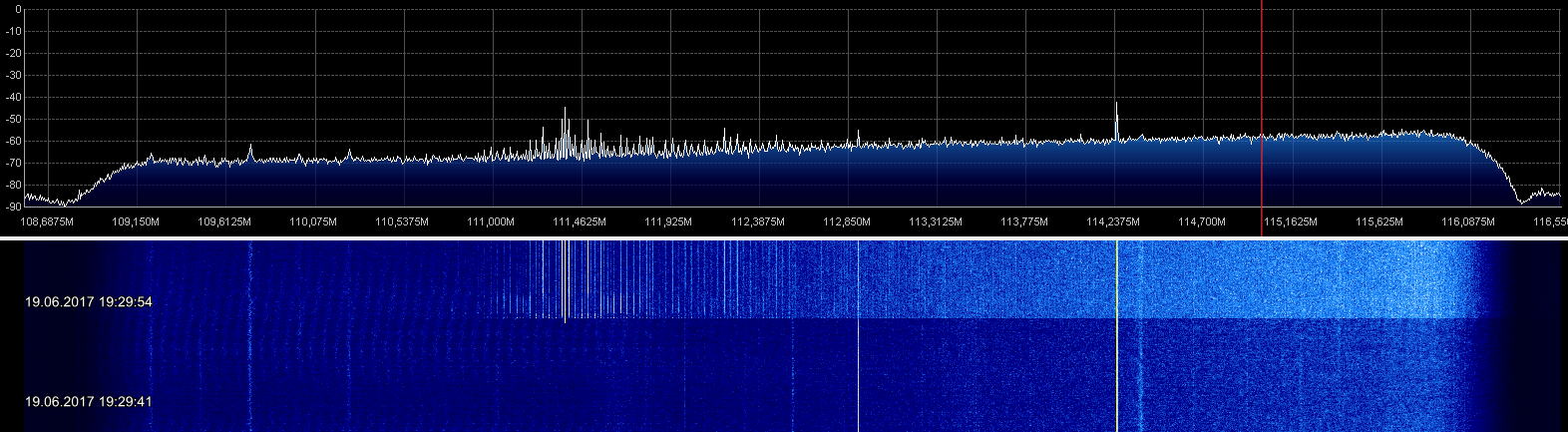
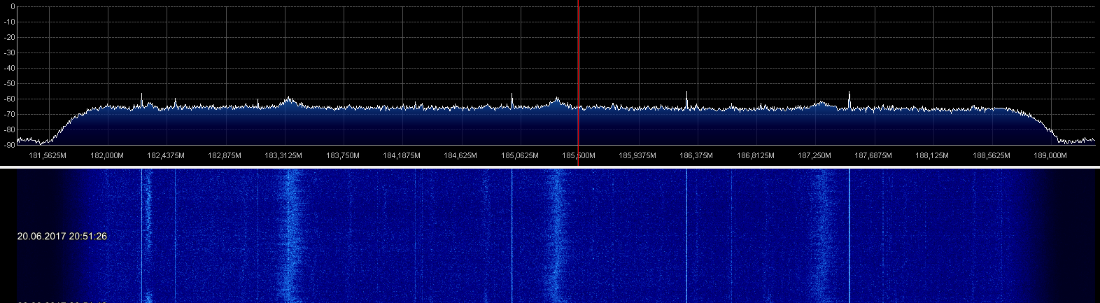
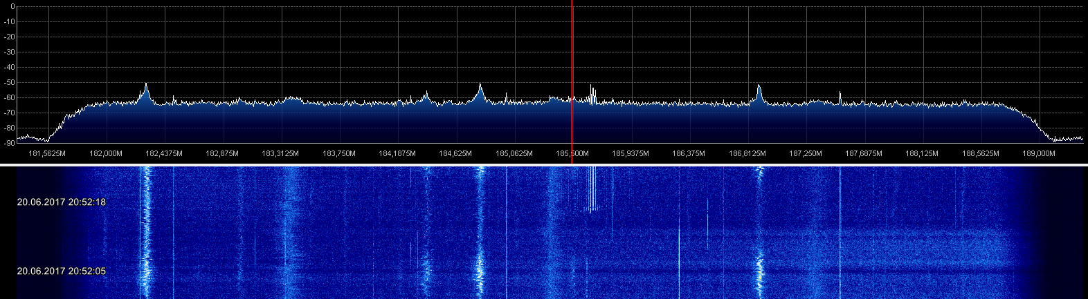
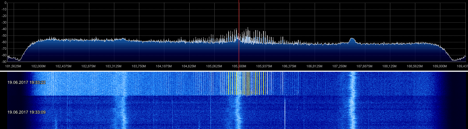
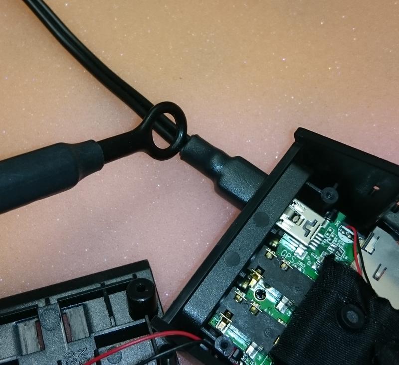
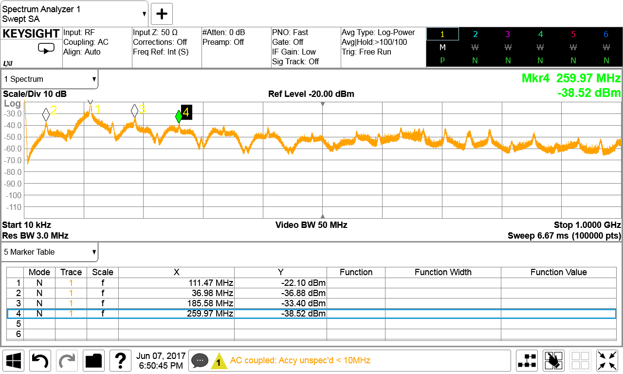
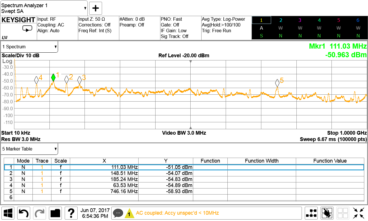
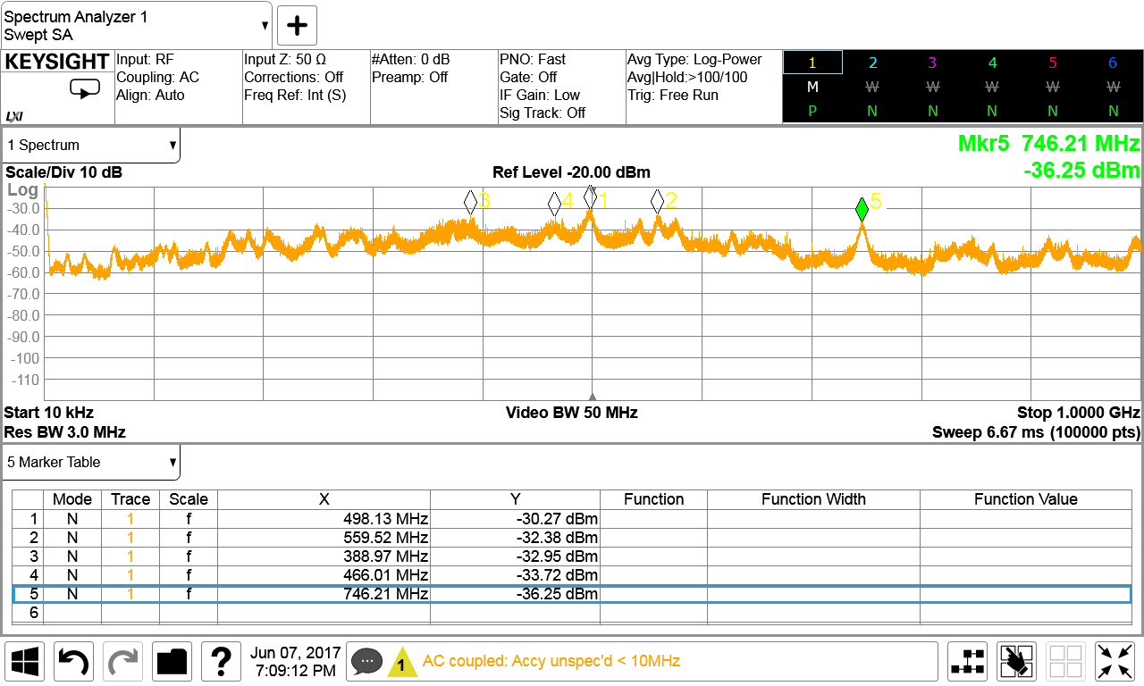
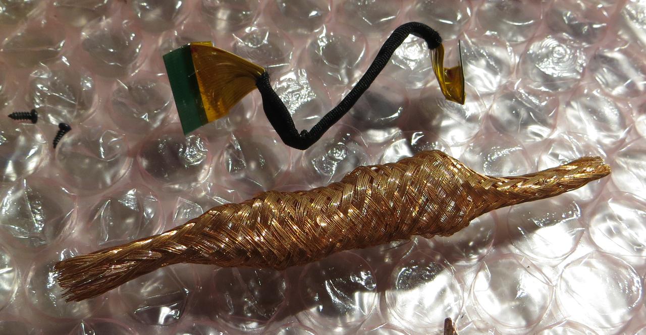
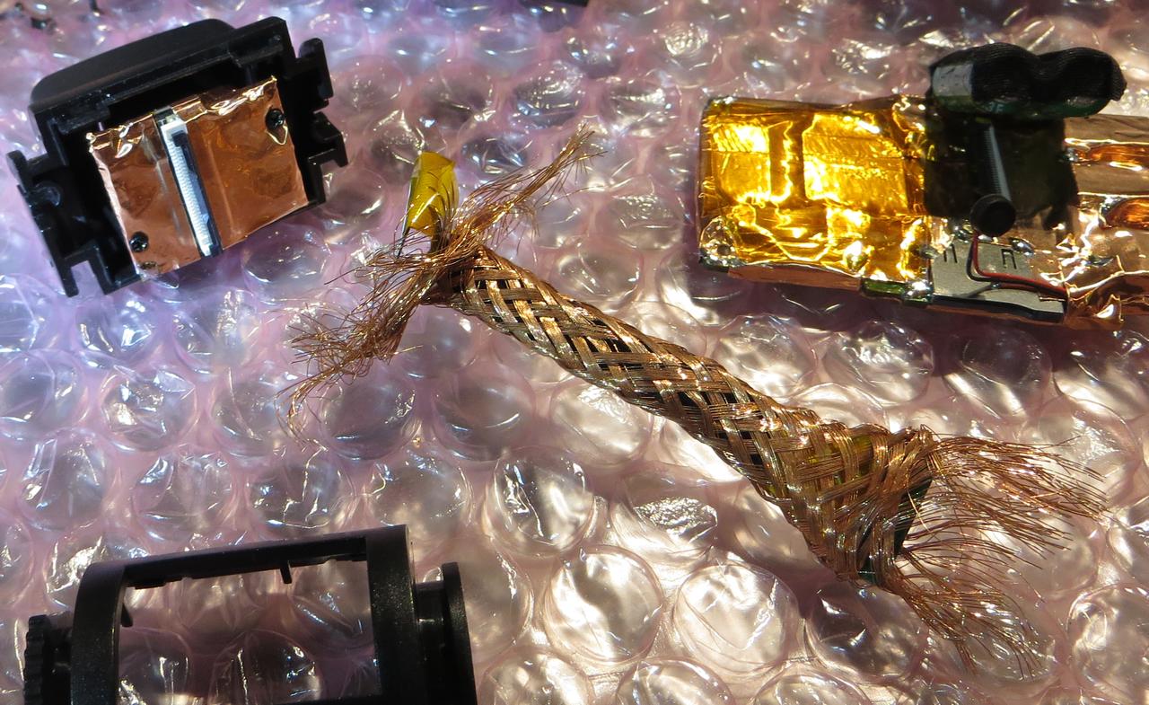
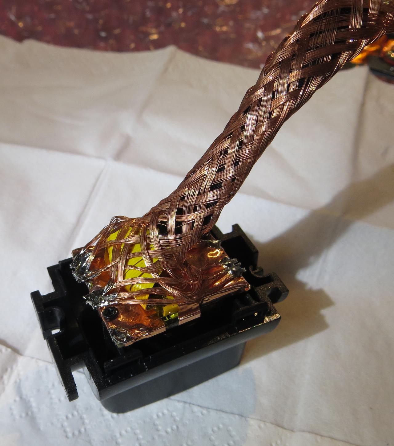
After swapping my car over a year ago I dind't install the SG9665GC again because back then I had issues with RFI. I could either use amateur-radio and listen to DAB+ radio or record the traffic and listen to music from the USB drive. Normal FM radio was also getting noisy when the SG9665GC was running. Back then the DAB aerial was mounted on the windscreen, approximately 50cm away from the cam. The USB power cable for the cam is DIY made of 2x 0,5mm² litz wire (AWG21 - AWG20) to fit around the windscreen and behind the airbags.
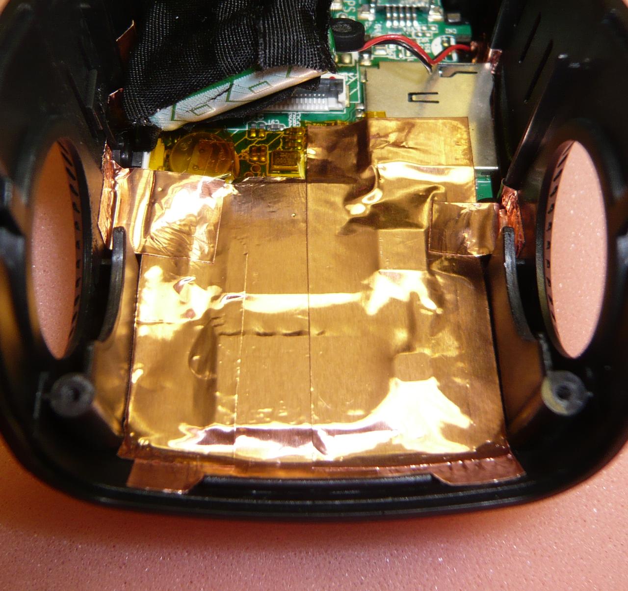
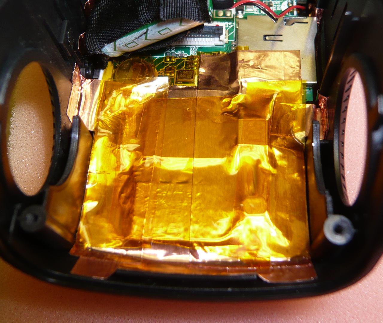
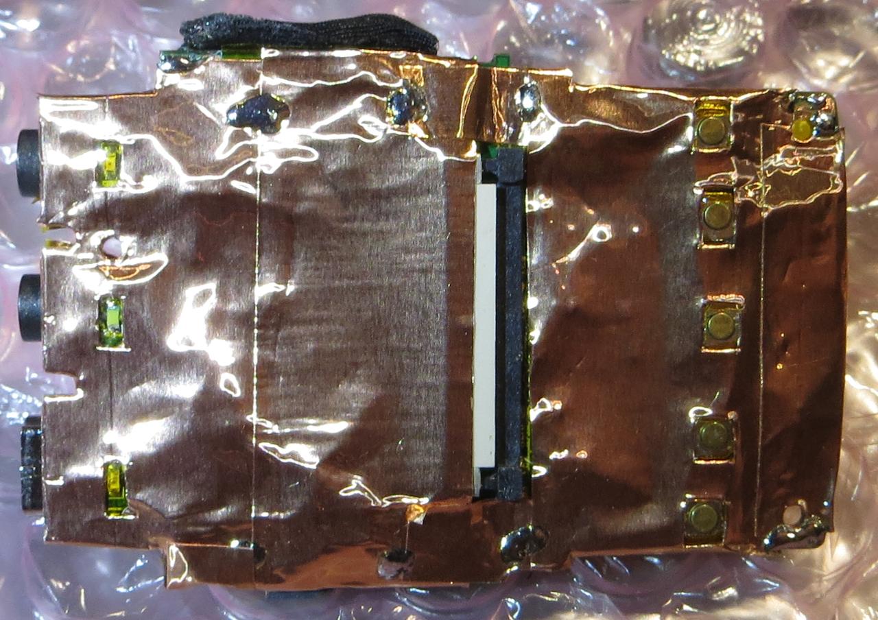
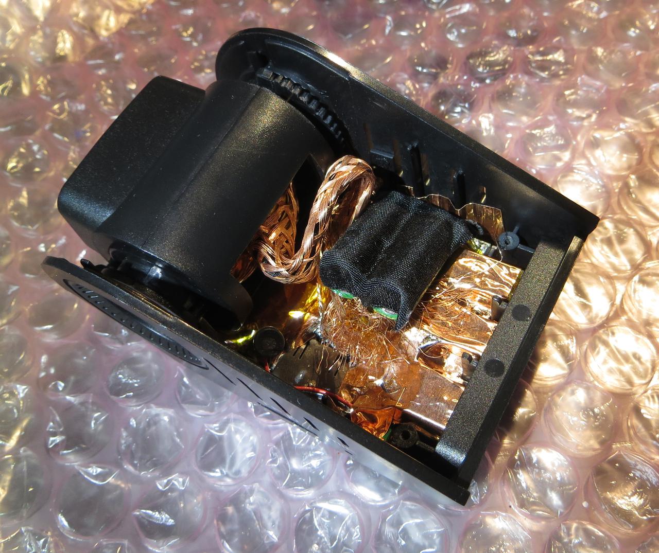
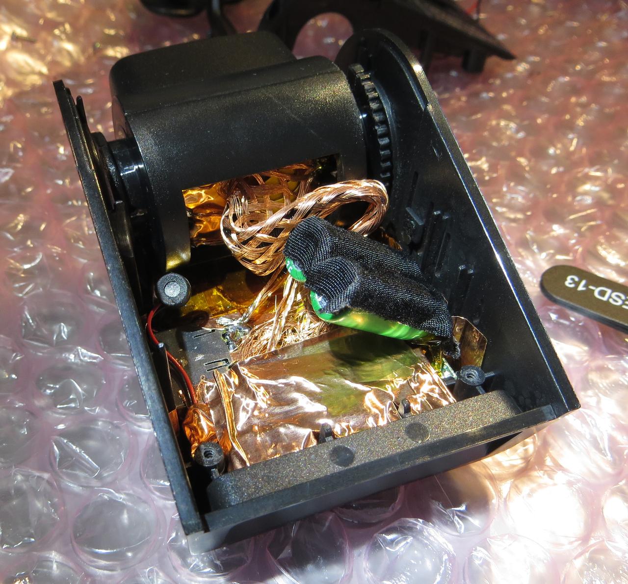
After the last RFI-thread I thought it would be a shame to let the SG9665GC rot in the basement. Because any warranty is long gone I could also do a teardown and some shielding attempts.
Now the SG9665GC is again mounted on the windscreen but the DAB aerial is mounted near the hatch, approximately 2m away from the cam.
Teardown
I couldn't find any teardown of the SG9665GC, so here we go. The Cam is V1.
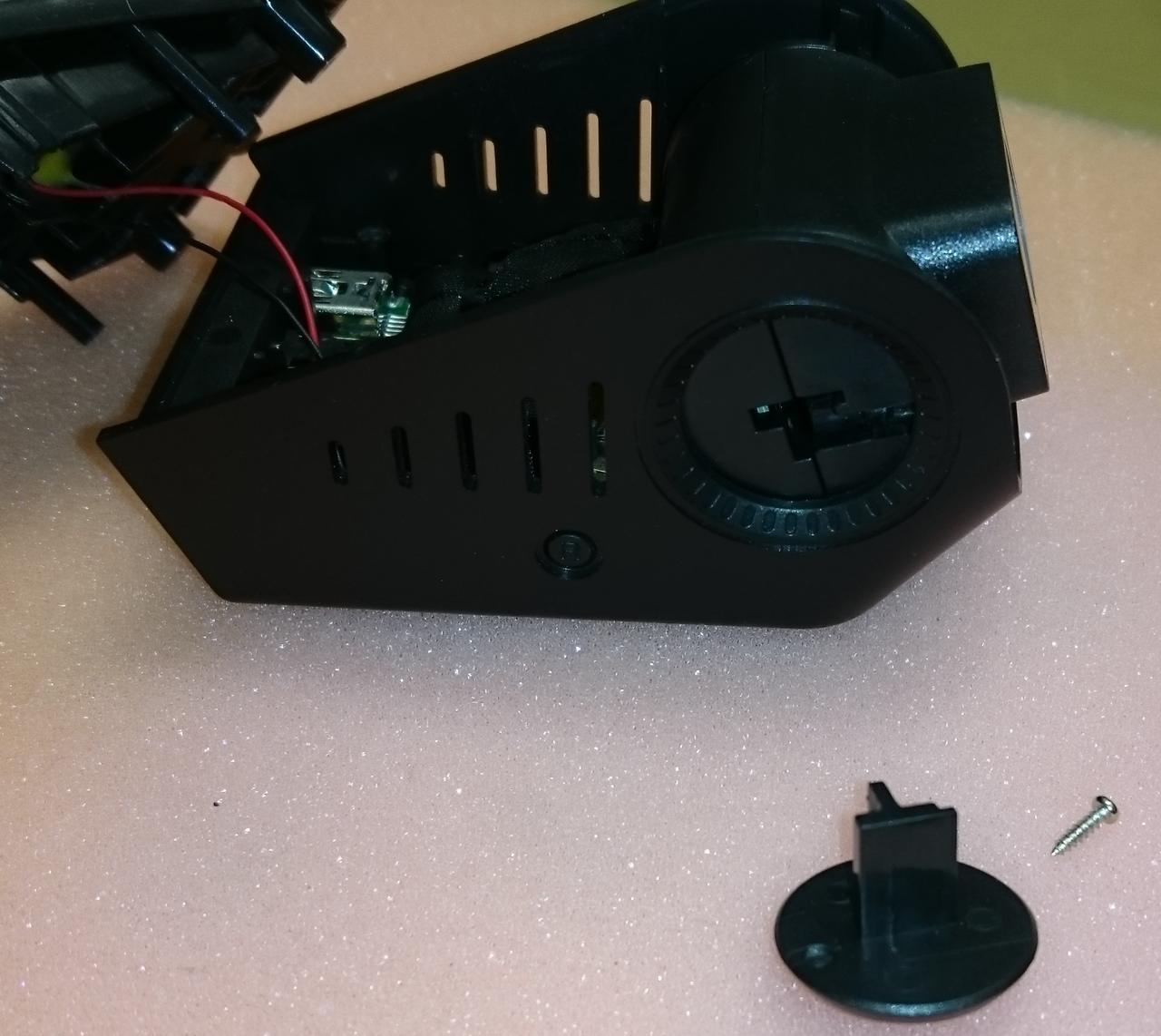
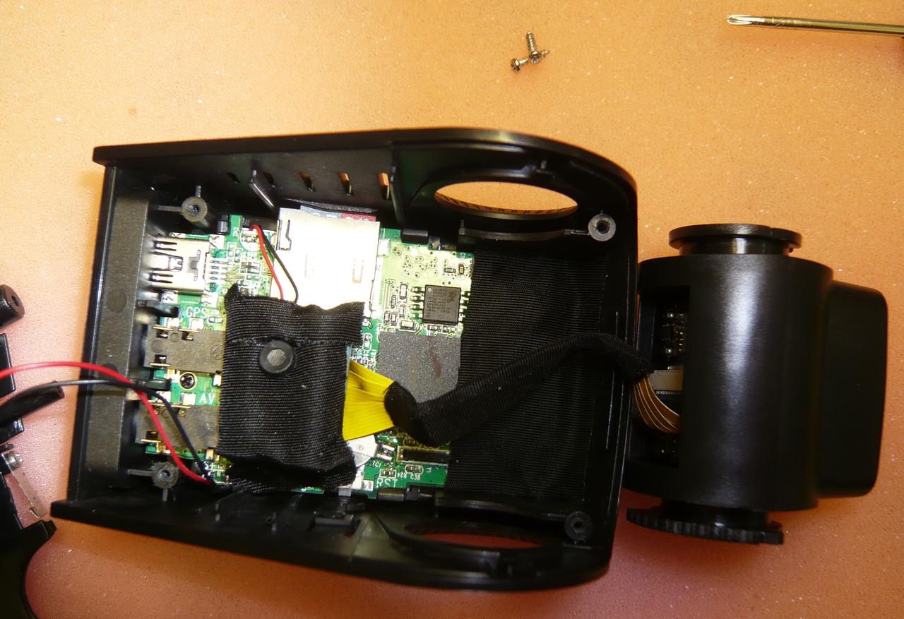
The case is held together by four screws, two might be covered by labels.
The camera must point upwards a little bit to disassemble, also mind the cable for the speaker.
To take out the sensor/lens assembly remove two screws which hold the adjustment knobs.
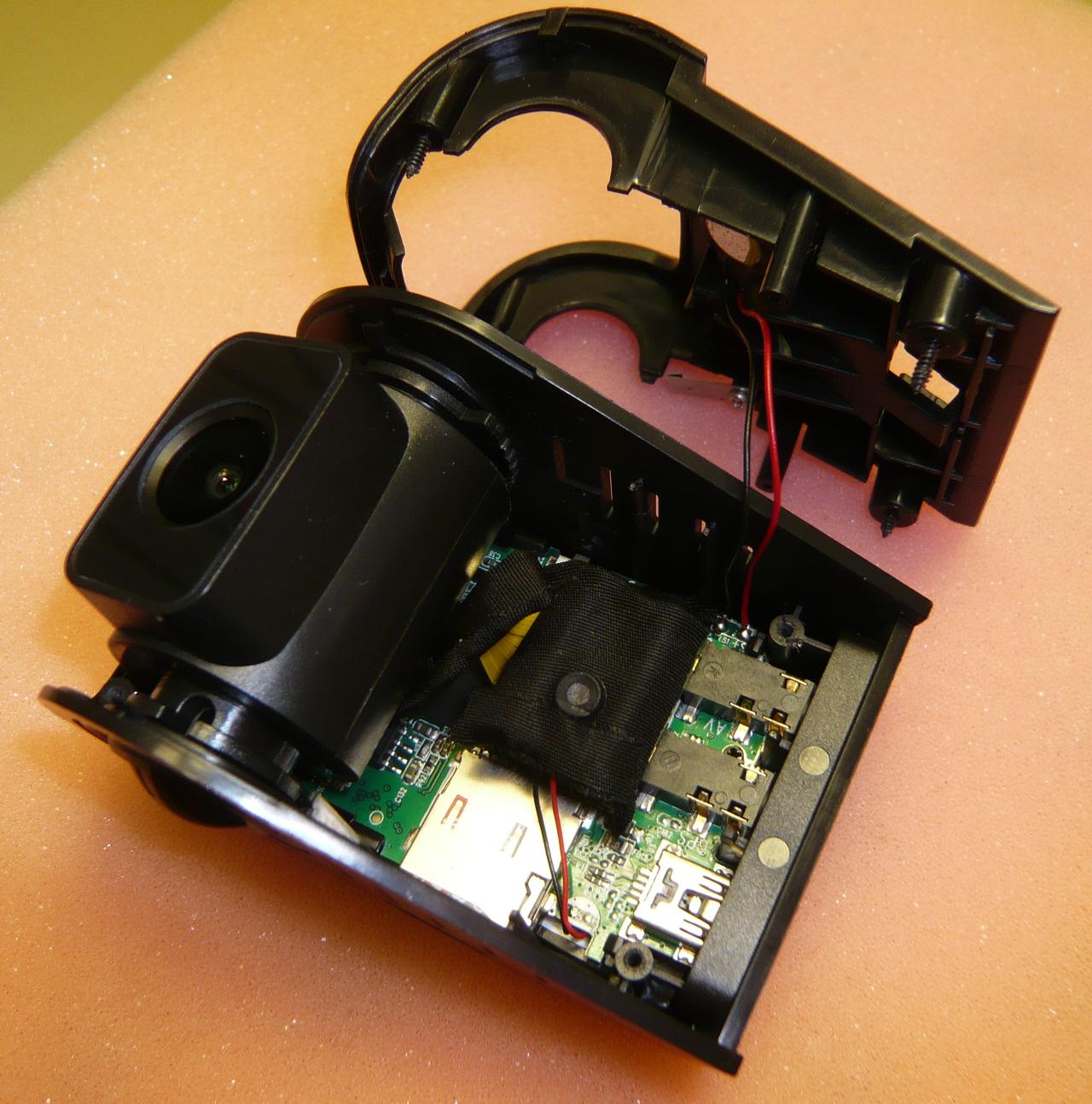
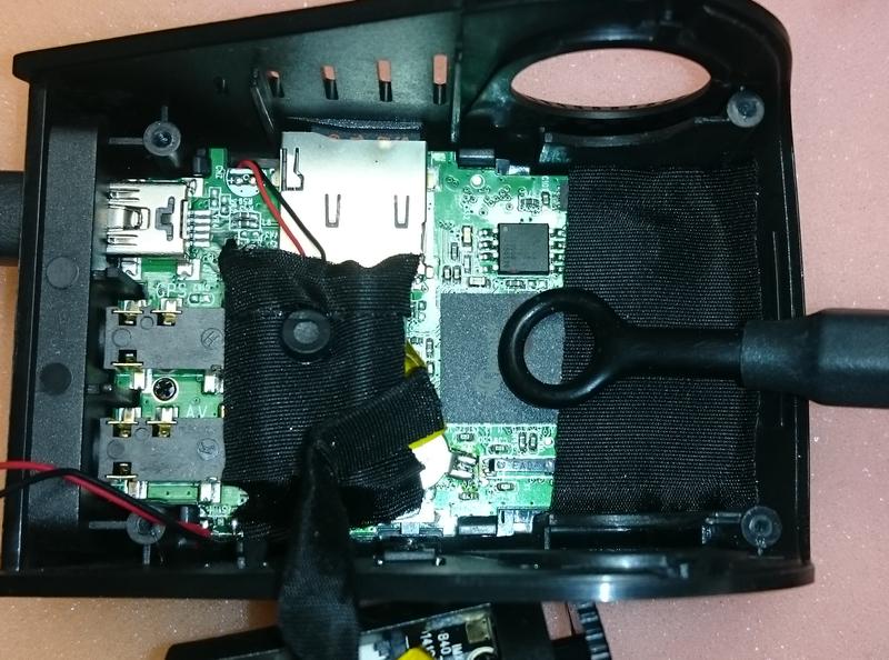
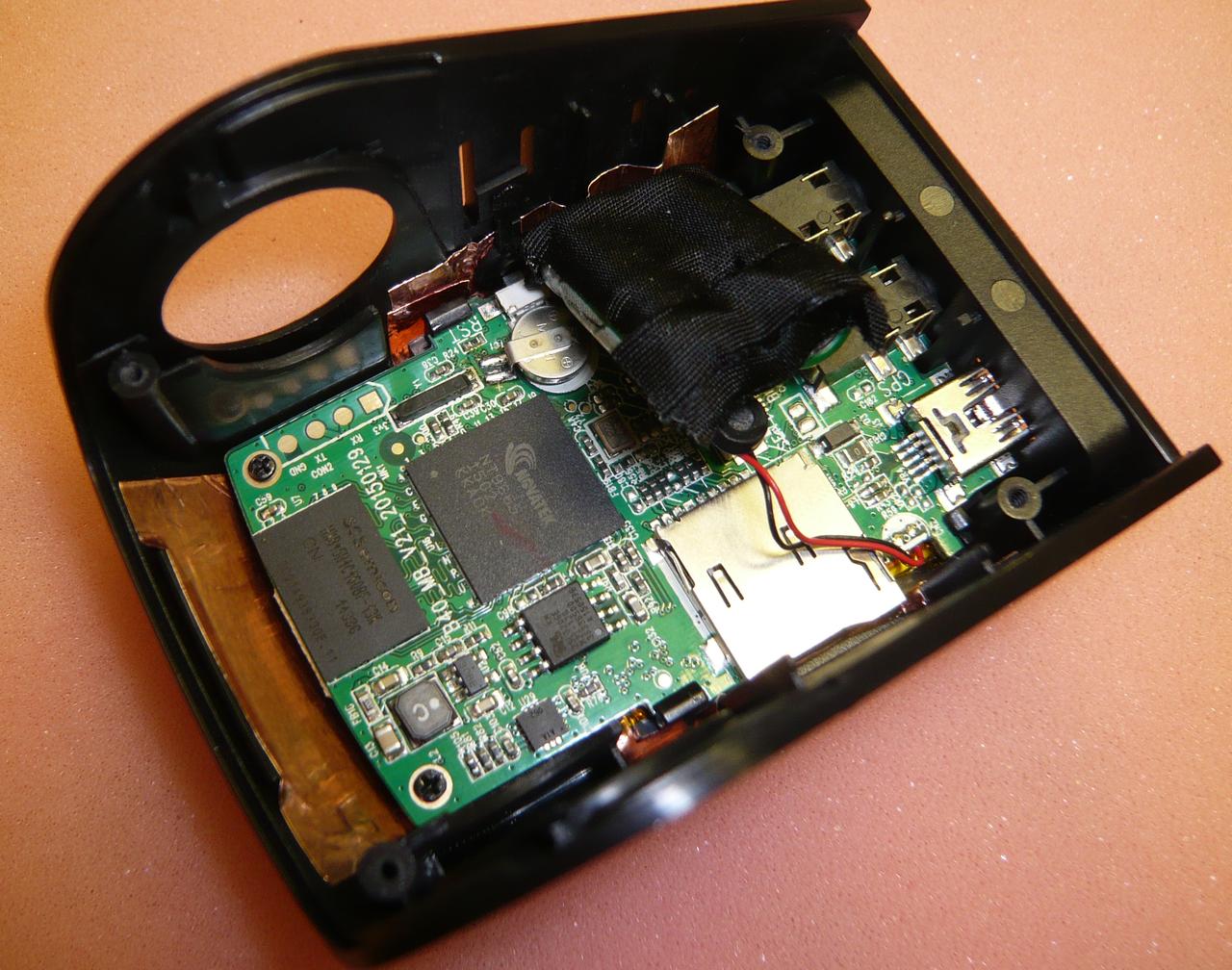
Now you can access the main PCB
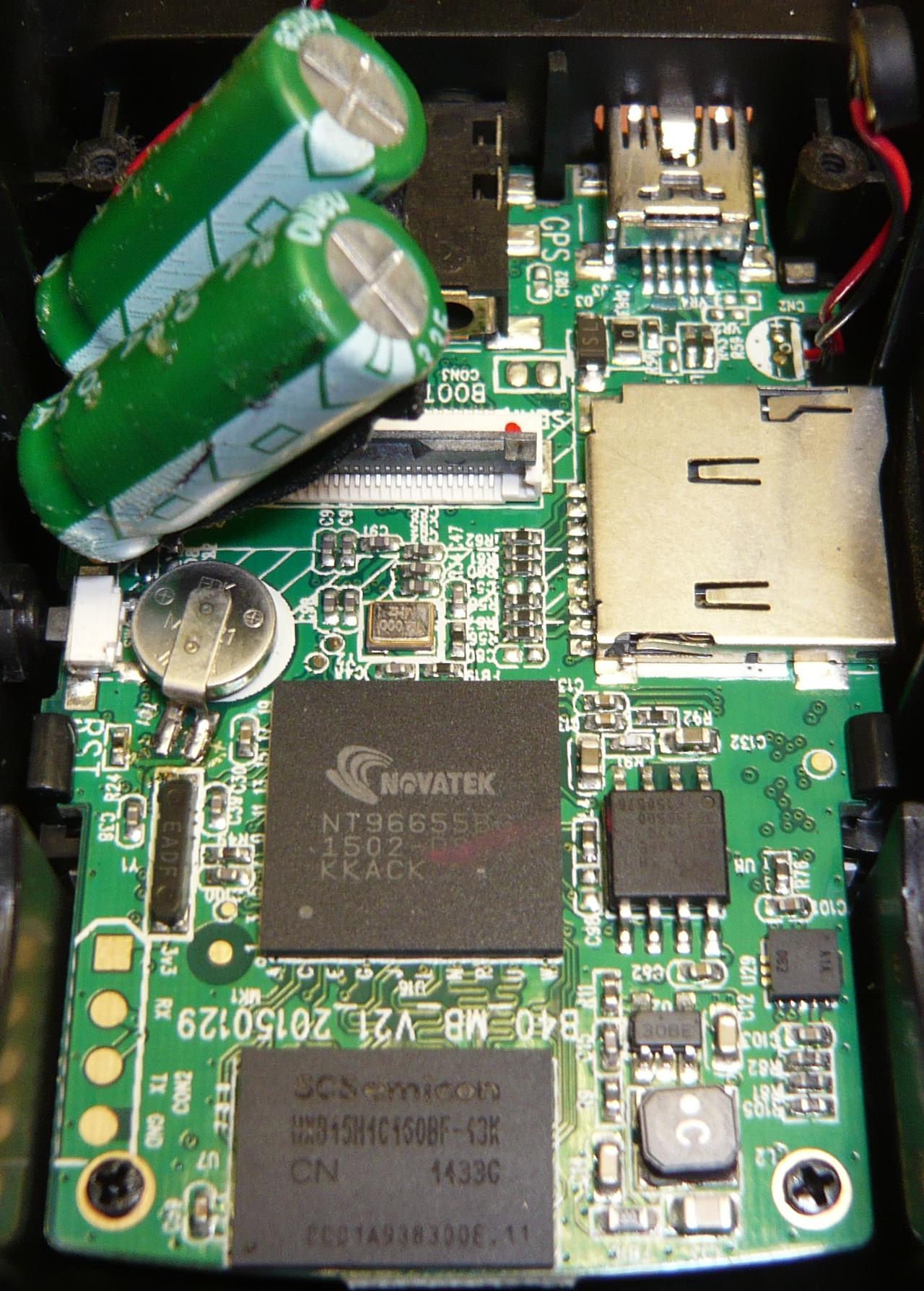
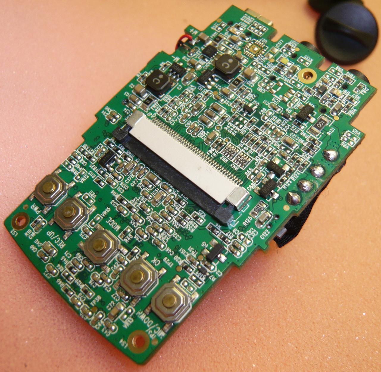
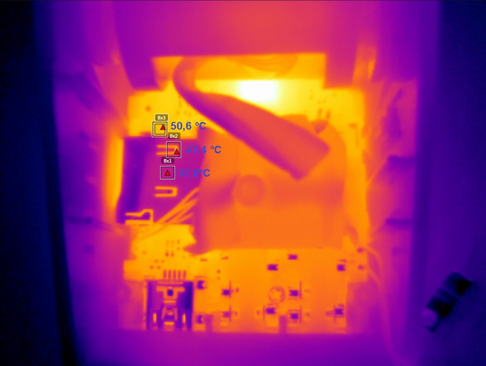
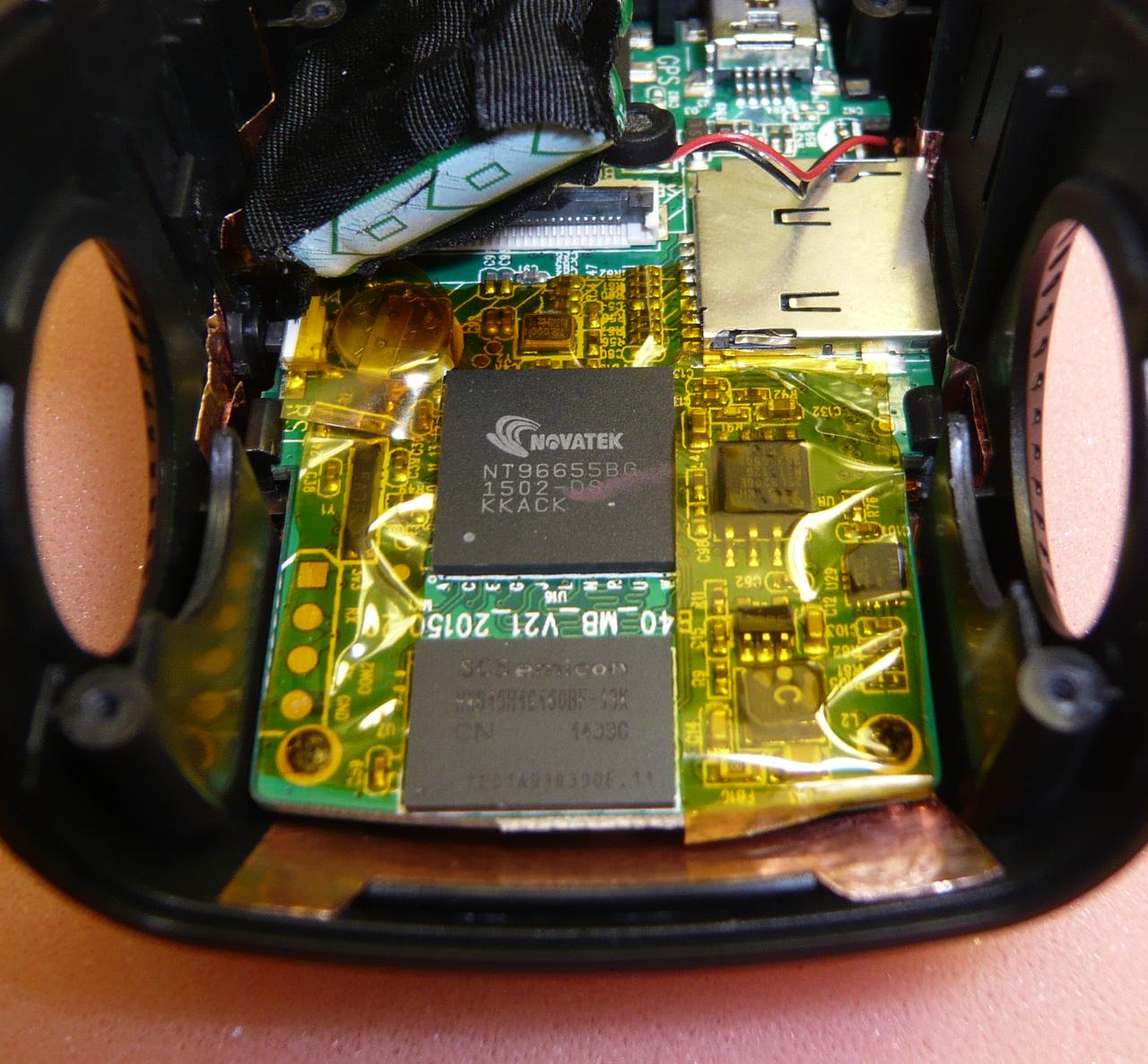
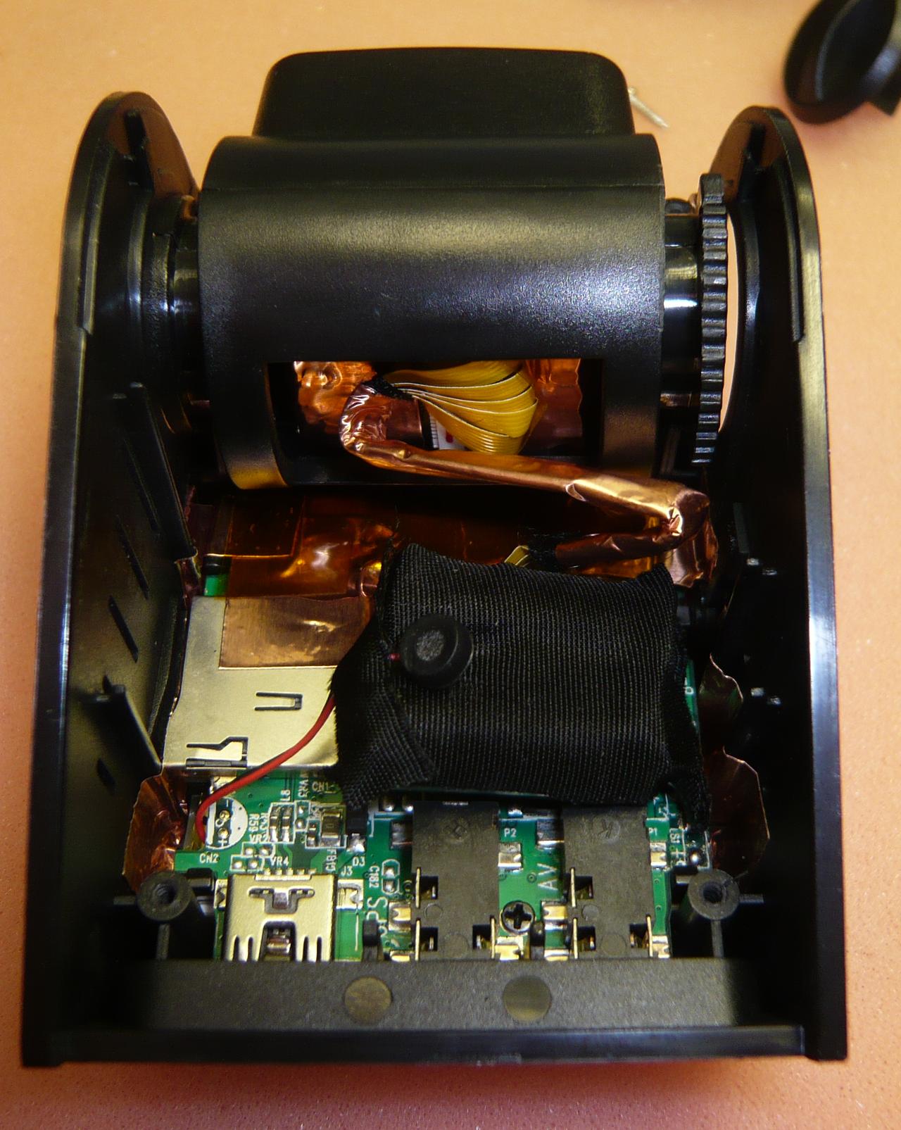
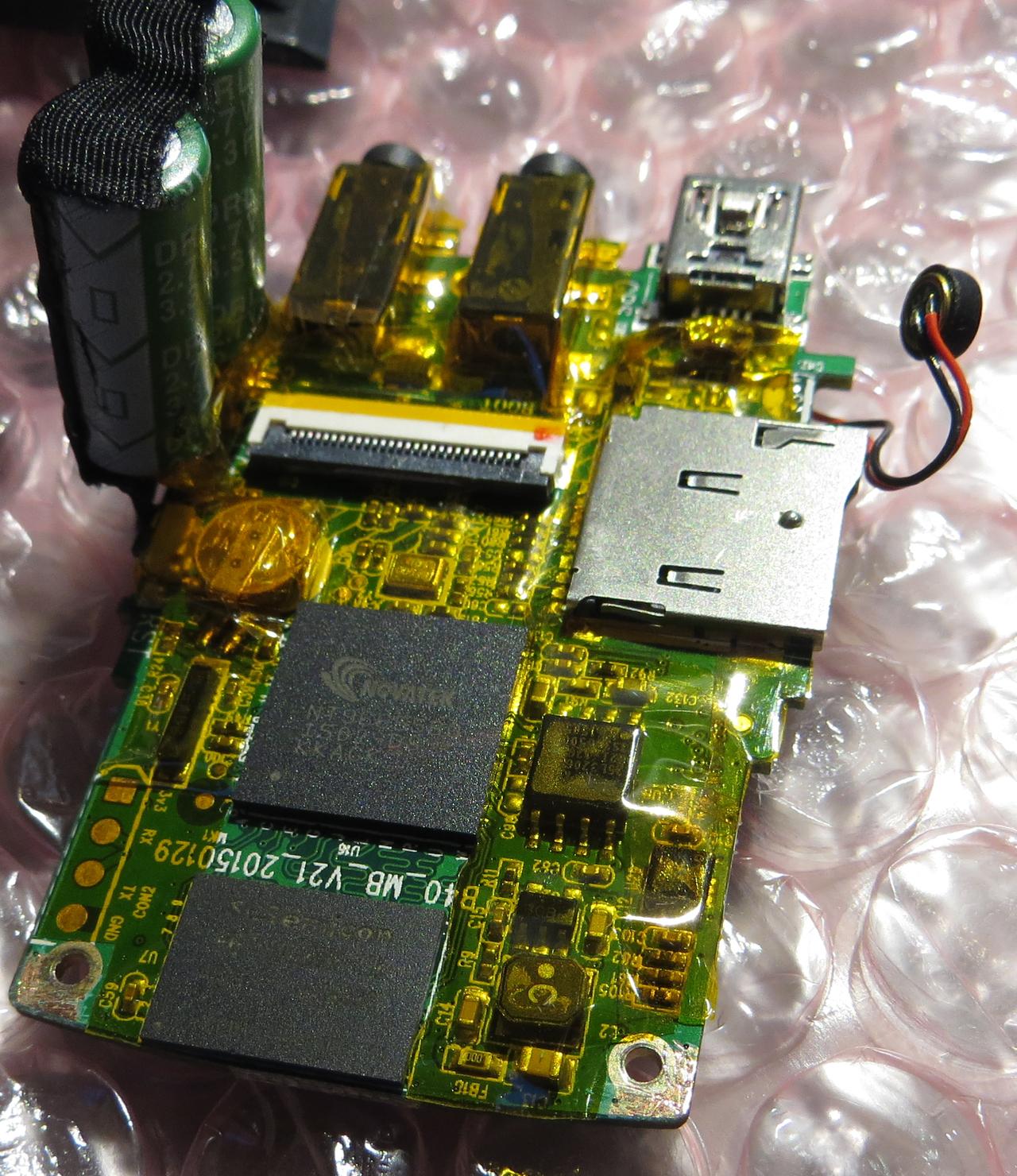
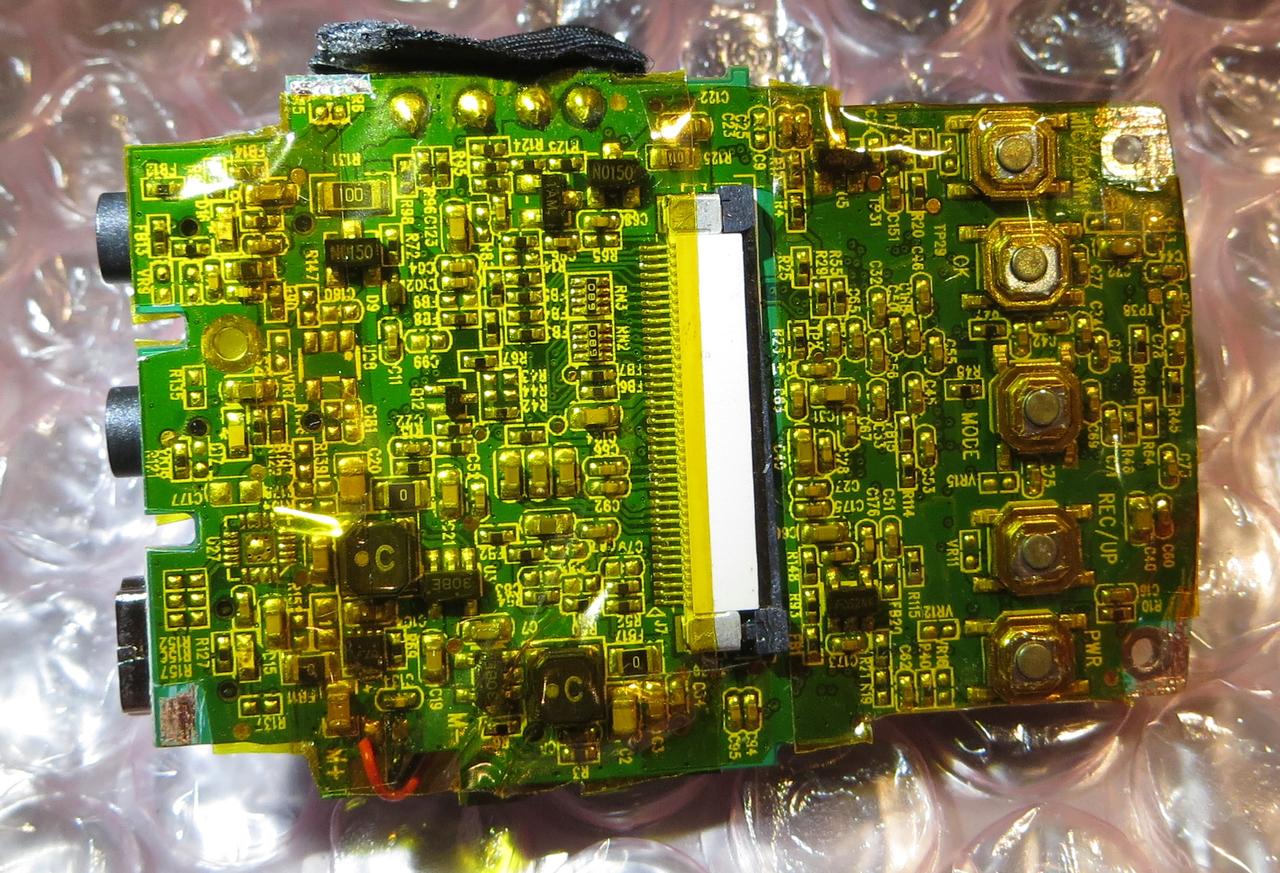
Remove the tape from the capacitors and mainboard. The PCB is marked with "B40 MB_V21_20150129"
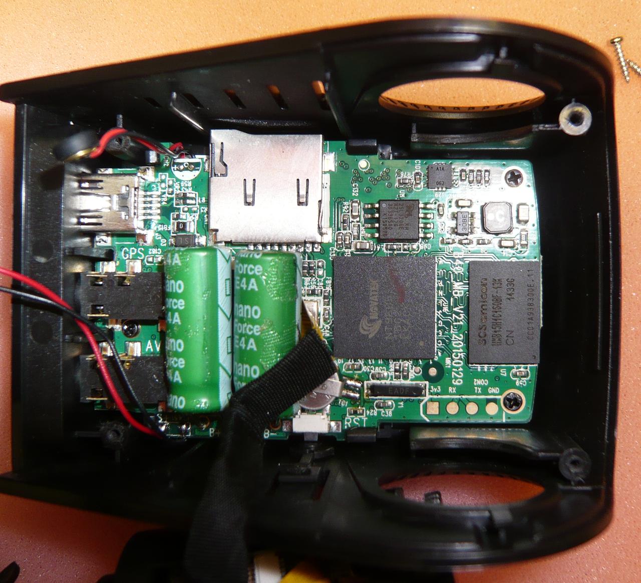
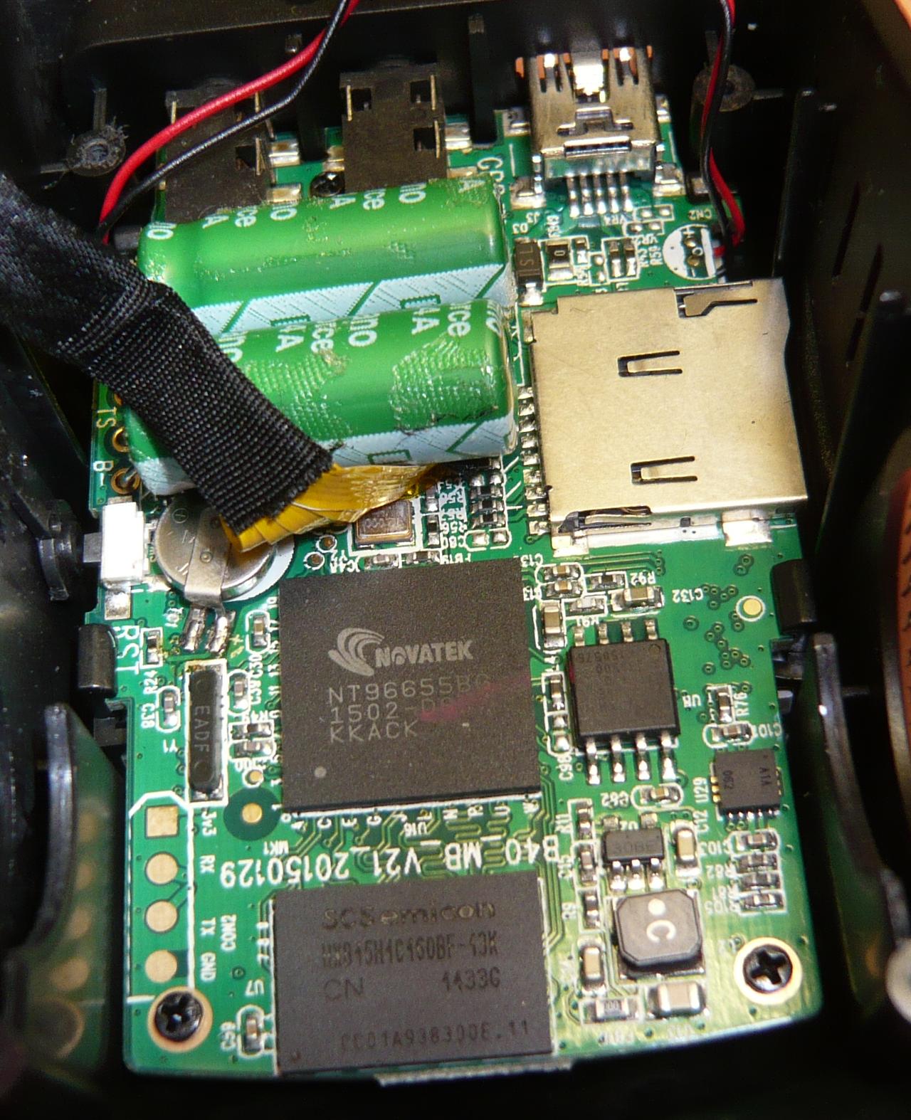
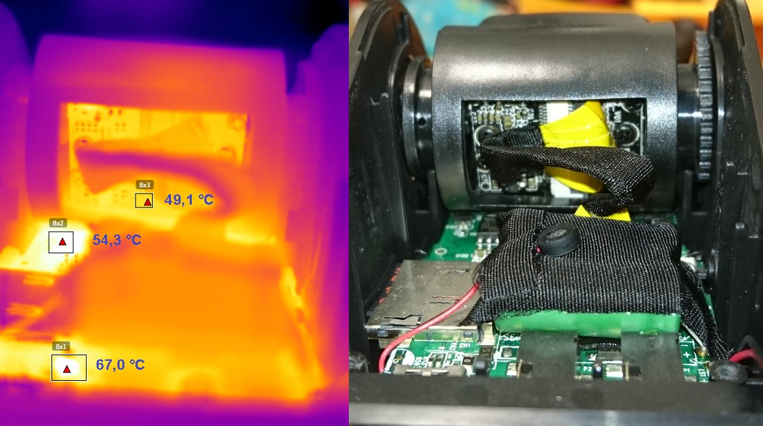
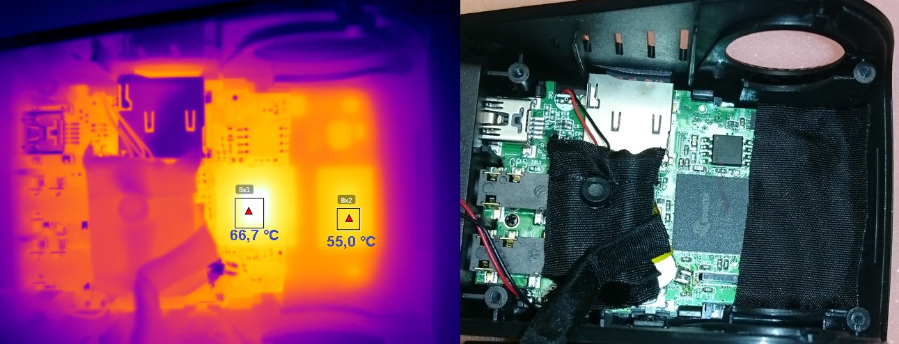
Now you can see the Novatec processor NT96655BG with RAM HXB15H1C160BF (couldn't find a datasheet, probably its 1Gbit) on the right and FLASH 25L3206E (32Mbit) on top. Below there is a battery and a crystal for the RTC and also some pads, probably for a serial interface.
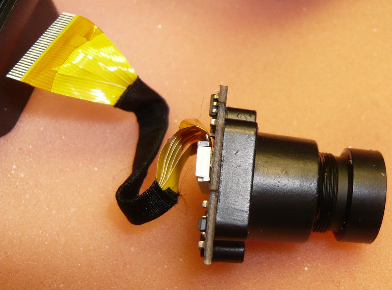
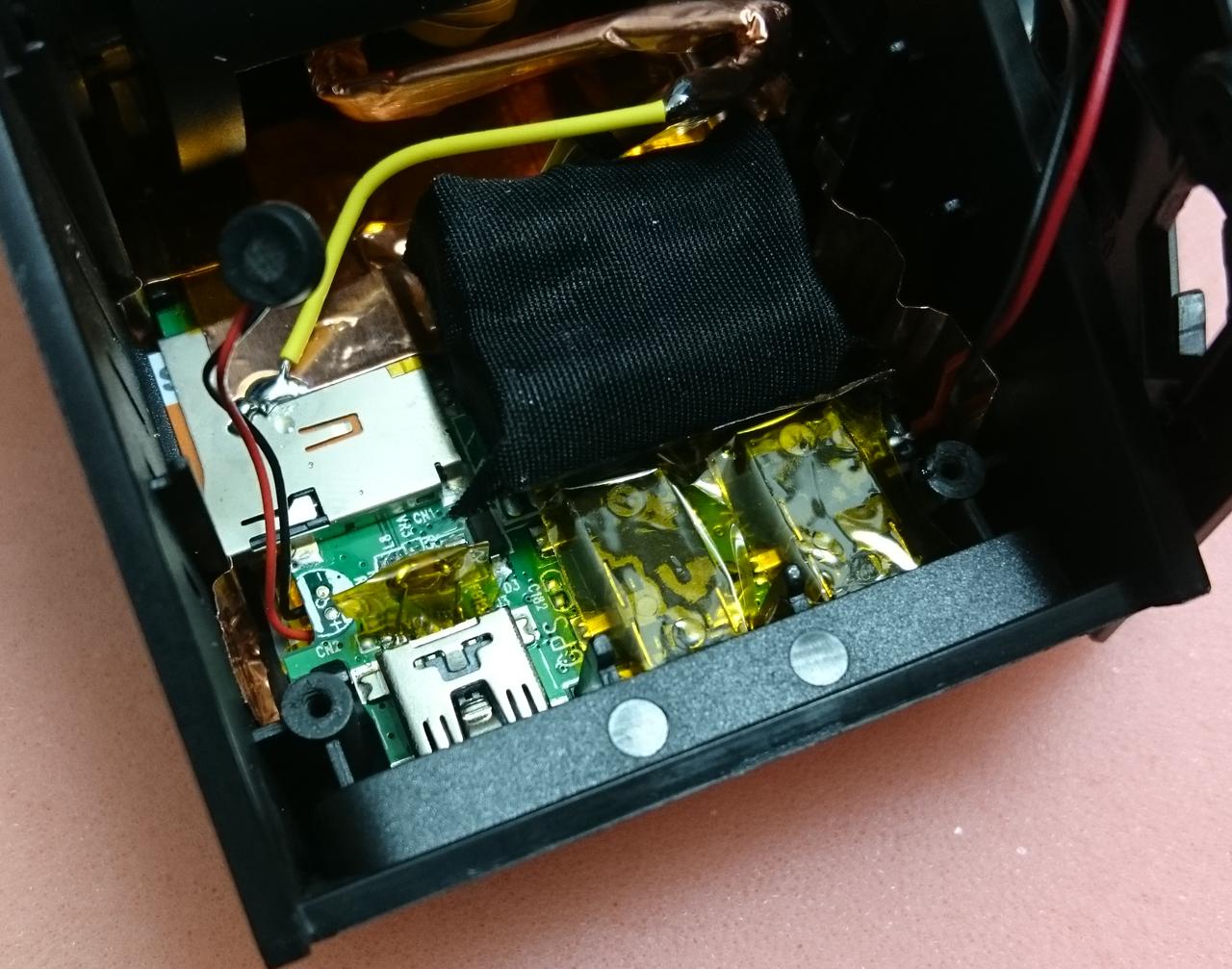
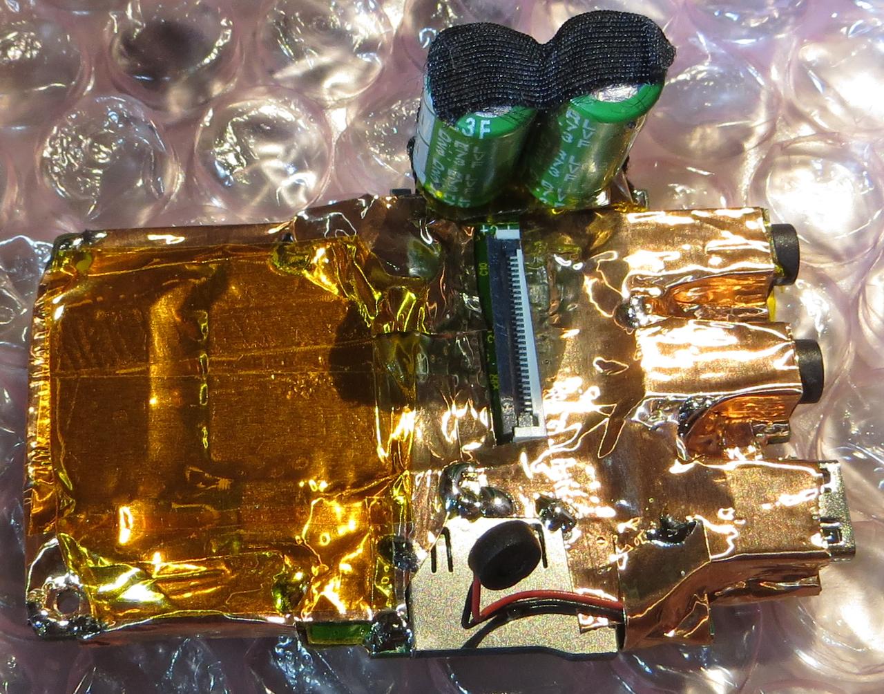
The connector for the FFC (flexible flat cable) towards the sensor/lens assembly is behind the caps
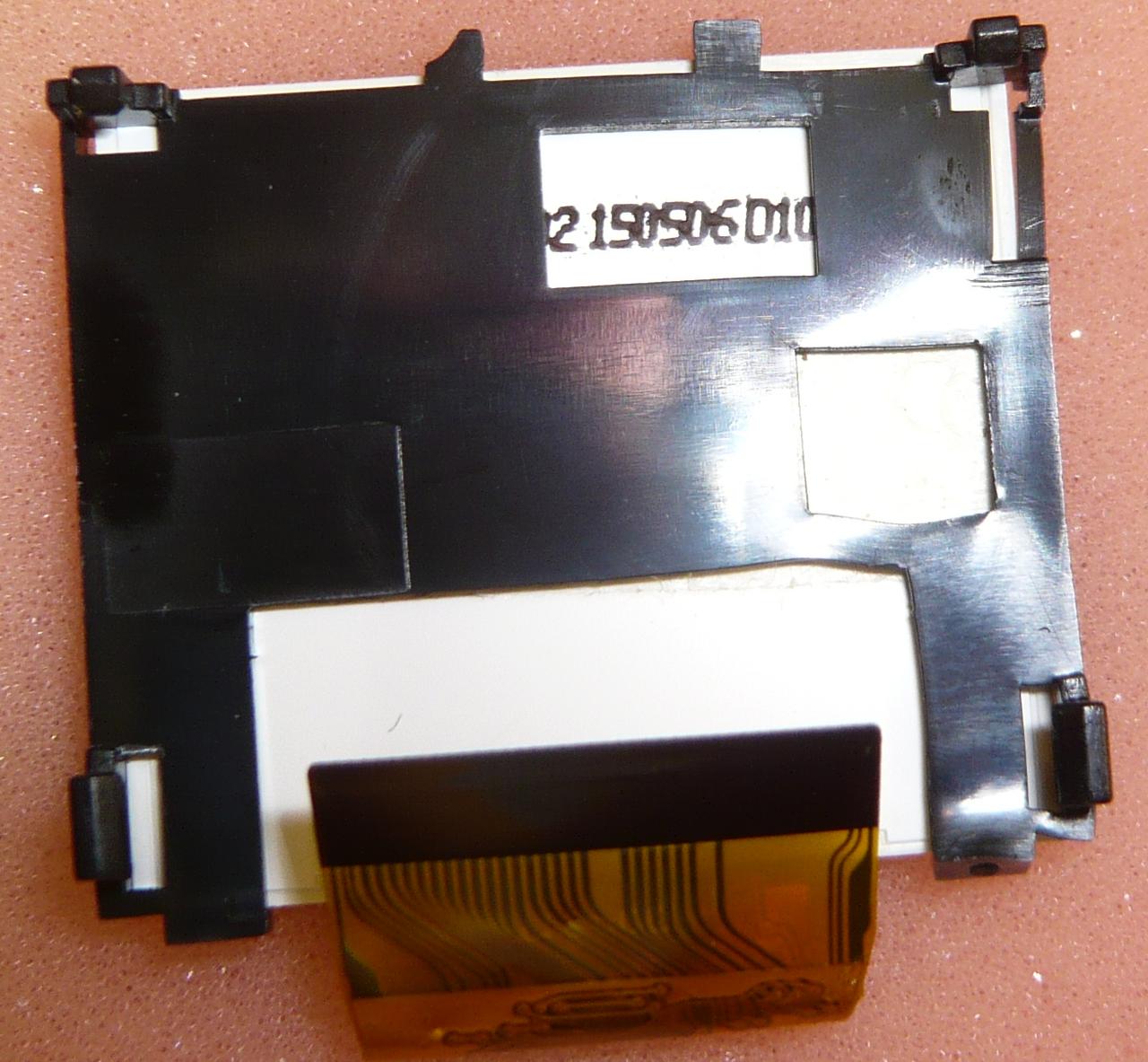
Lift the caps carefully, they are attached to the FFC and connector with adhesive tape
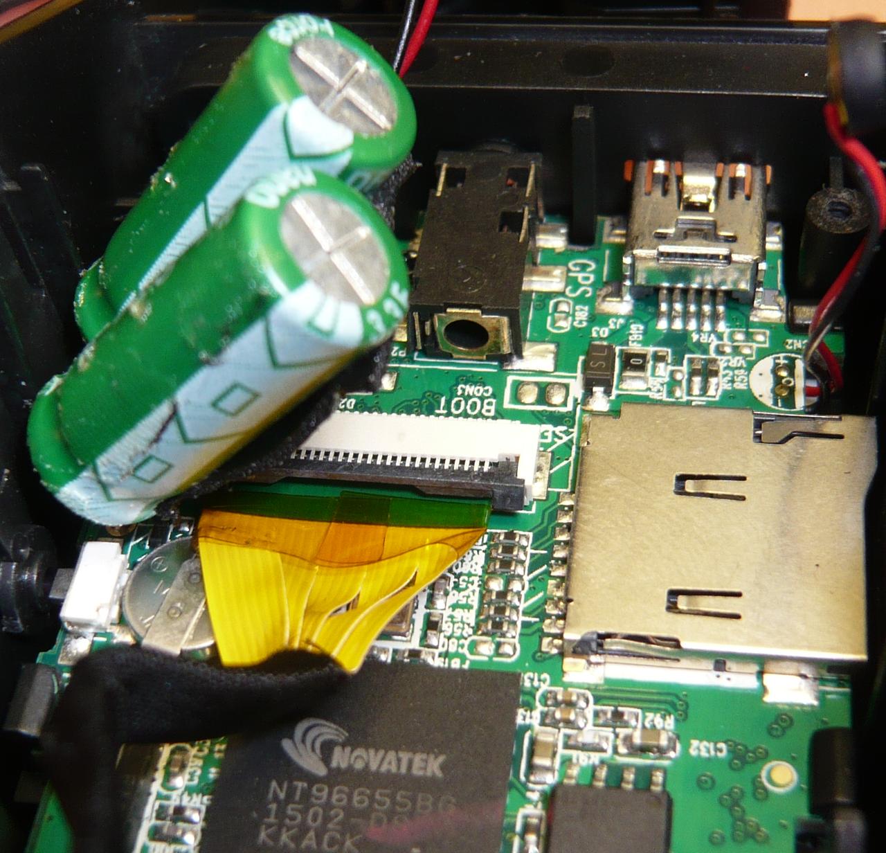
Lift the black clip on the connector upwards to disconnect the FFC. Don't forget to mark the FFC...
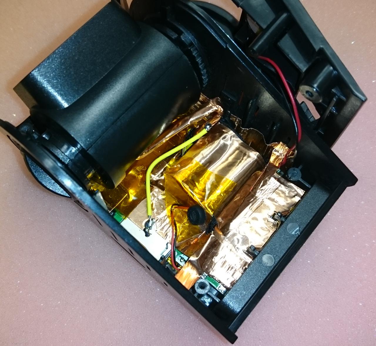
Below the FCC the main crystal/oscillator was hidden
Now you can continue with the sensor/lens assembly
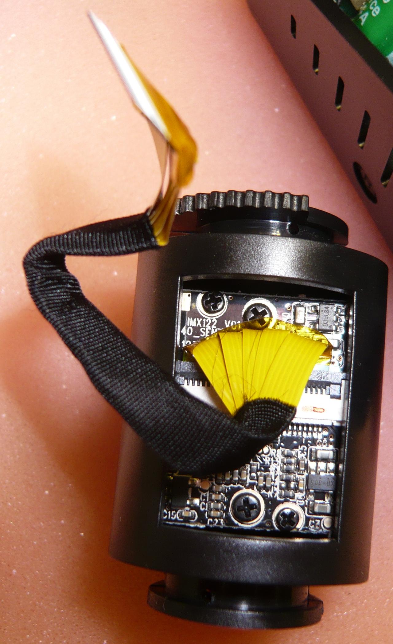
The case consists of two plastic part holding together with four clips. The PCB is screwed to the front of the case
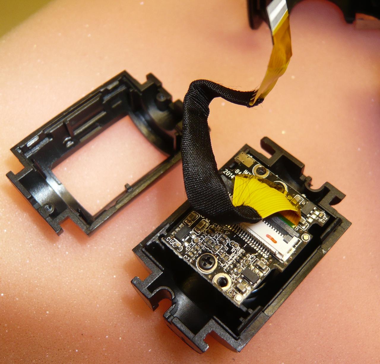
The two bigger screws in the middle of the PCB hold the lens assembly, the screws diagonally hold the PCB.
Unscrew the PCB to get out the sensor/lens assembly
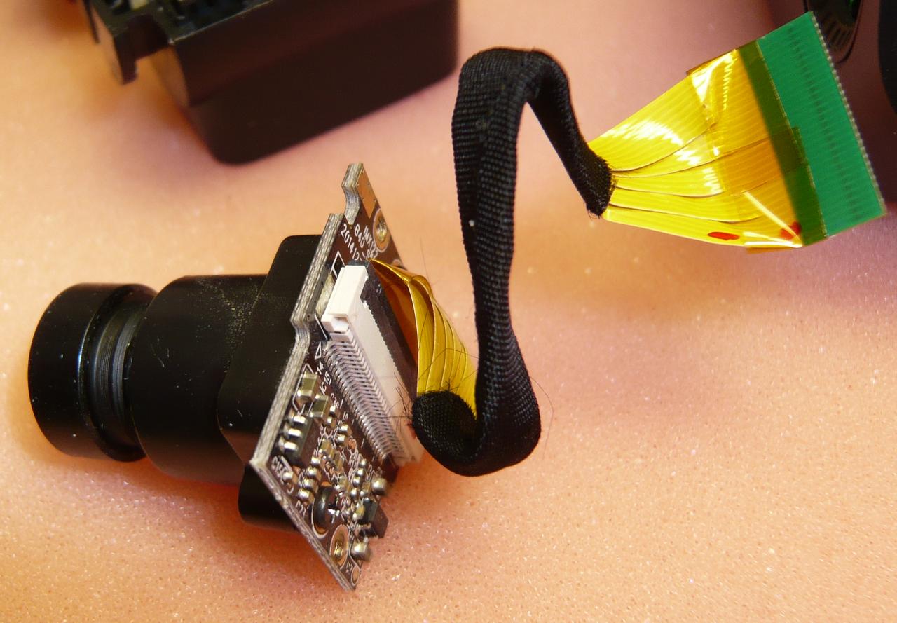
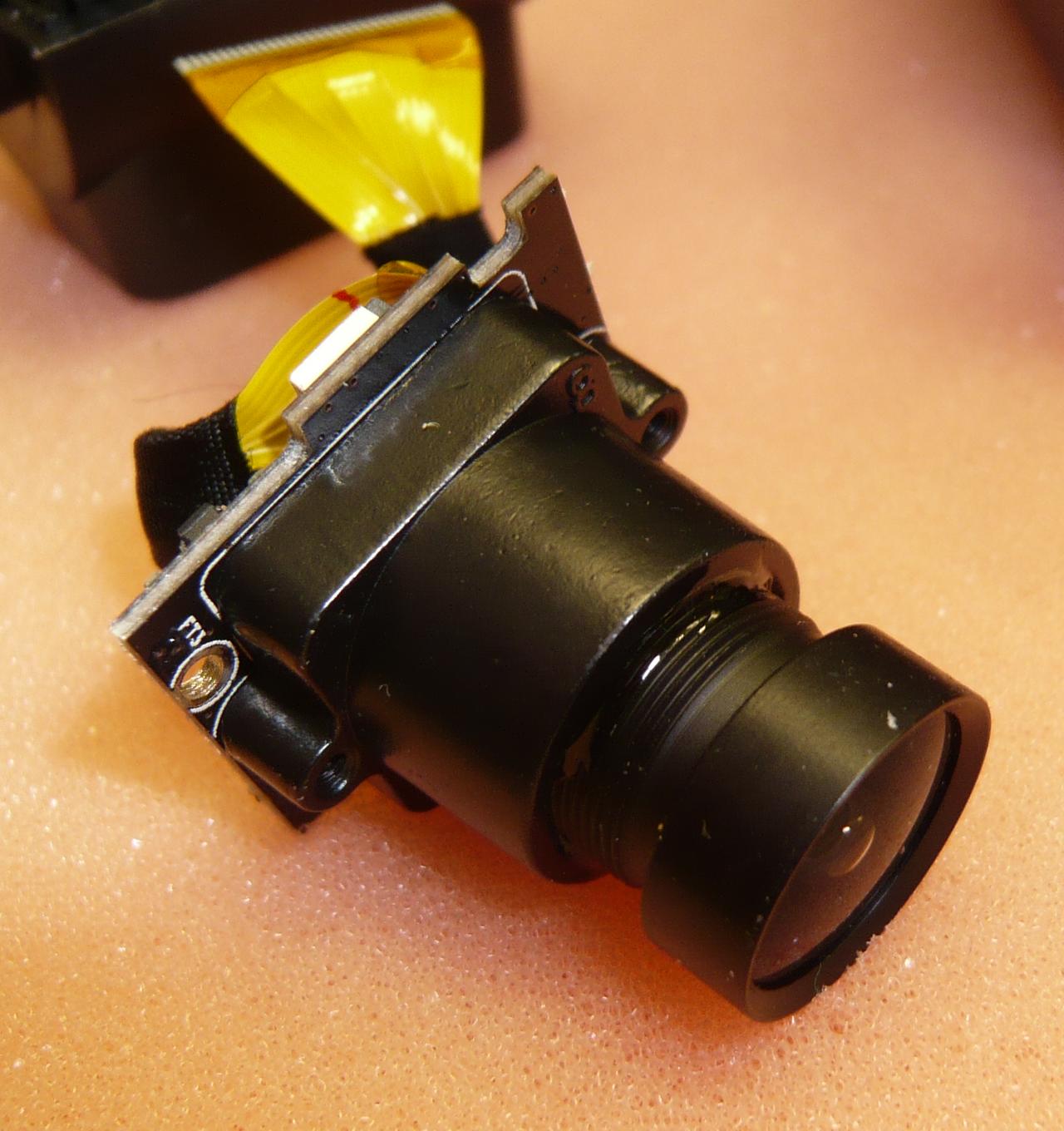
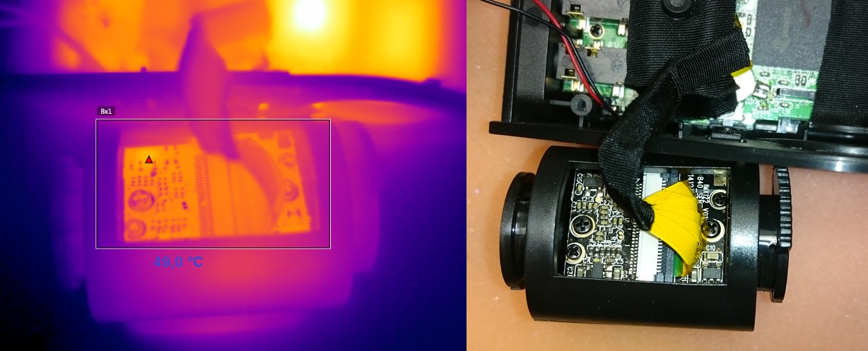
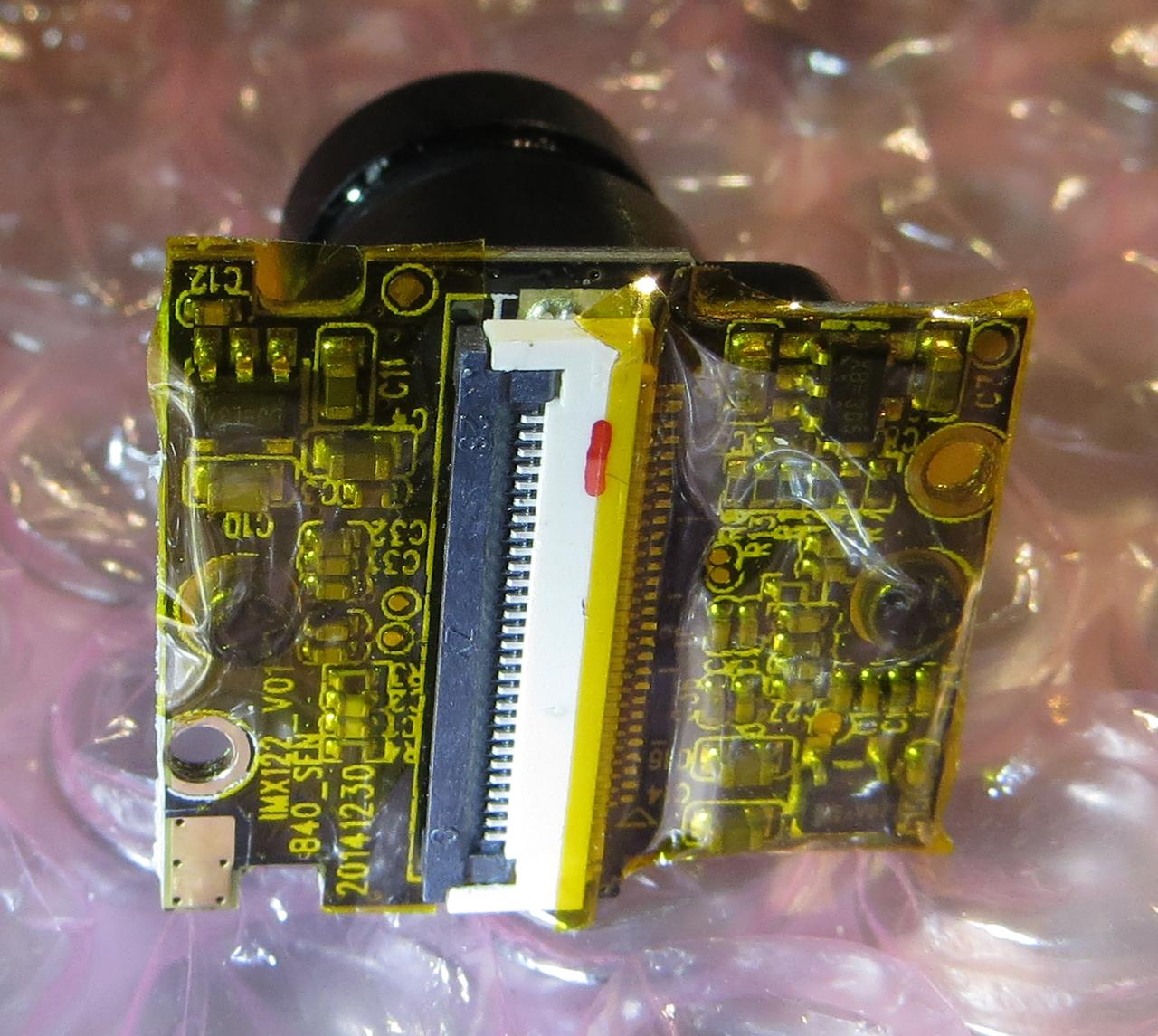
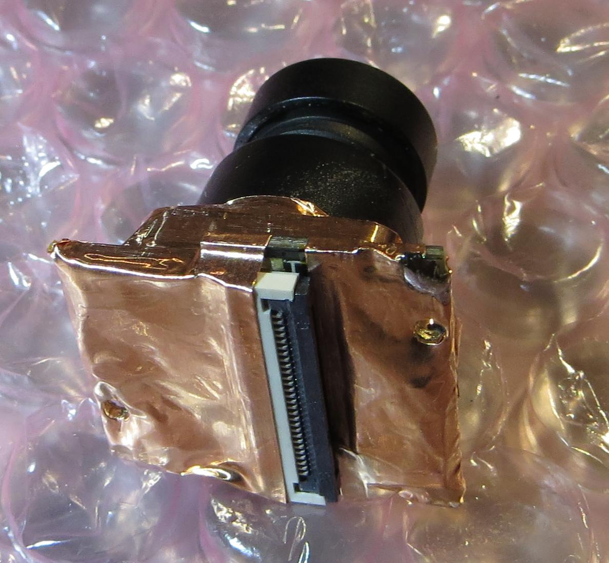
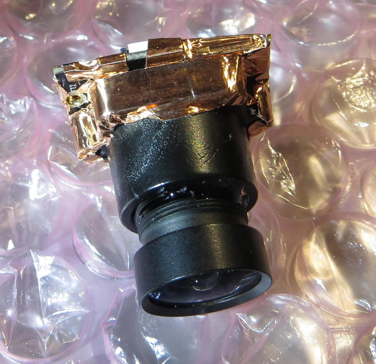
As promised the lens and lens holder is made of metal. The lens is glued in with a good amount of glue which does not come of easily (in case you want to adjust the focus).
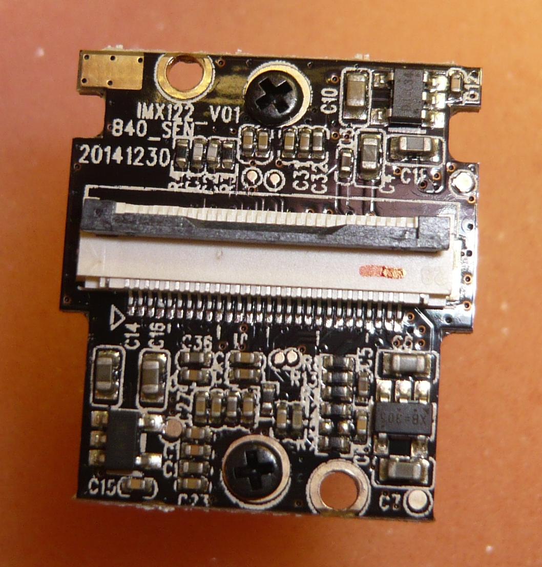
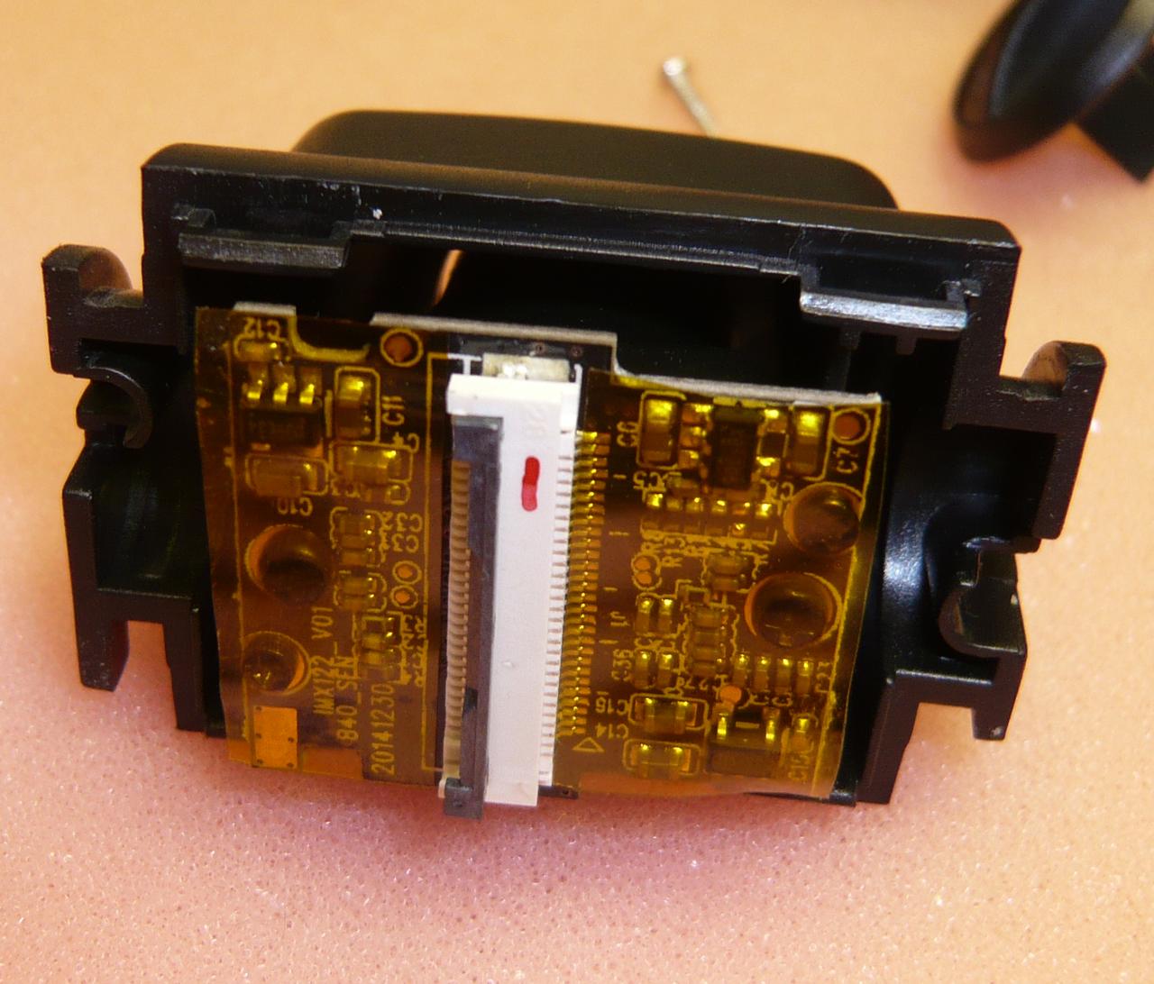
The sensor PCB is marked with "IMX122_V01 840_SEN 20141230" and contains probably the low noise LDOs (low dropout linear voltage regulator) requiered for the sensor
With the sensor/lens assembly removed you can unscrew the three screws holding the mainboard and remove it
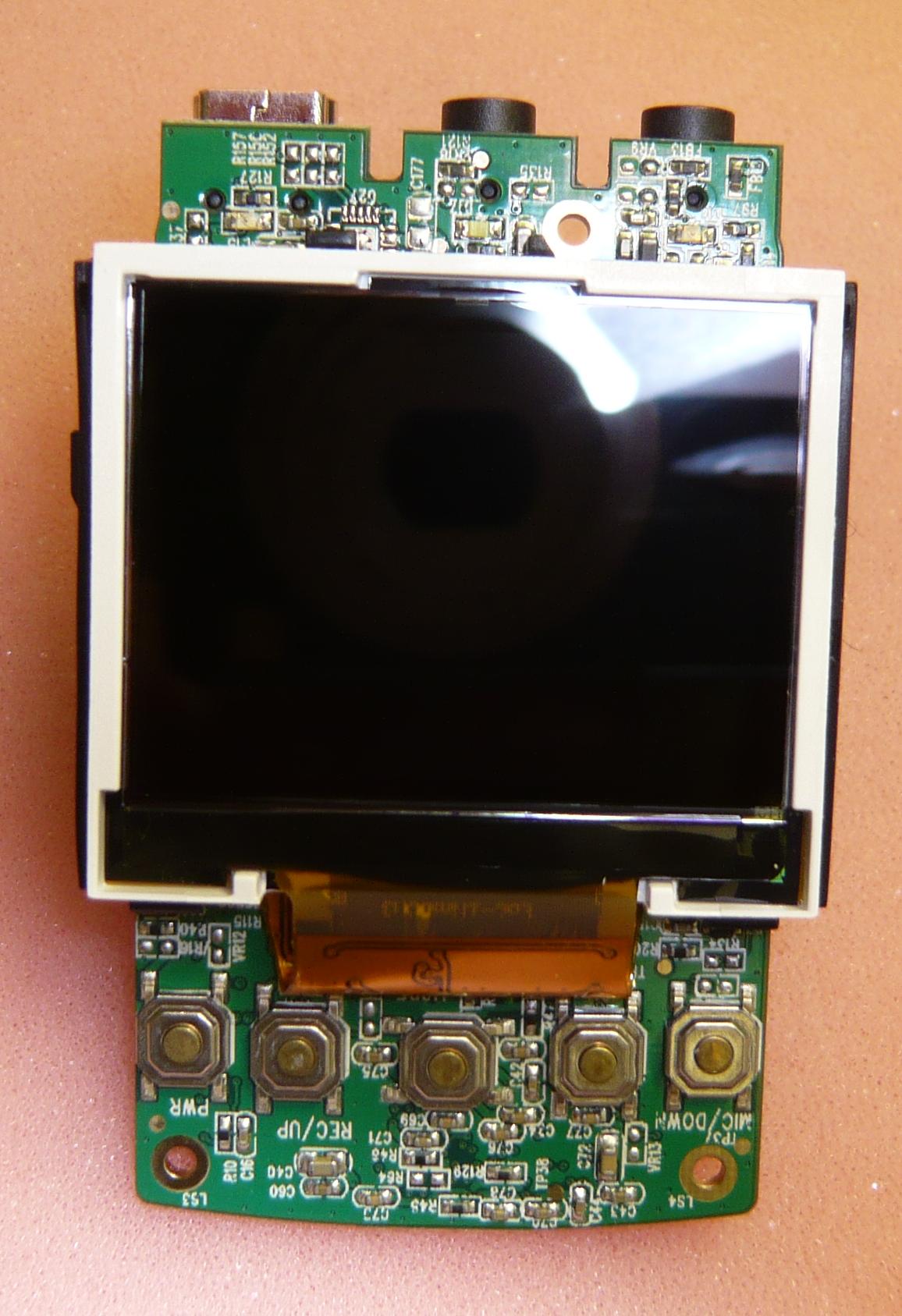
Buttons
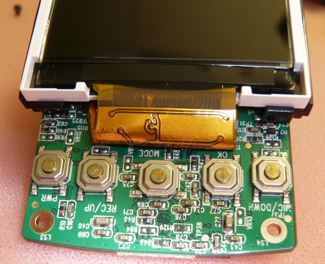
And LEDs
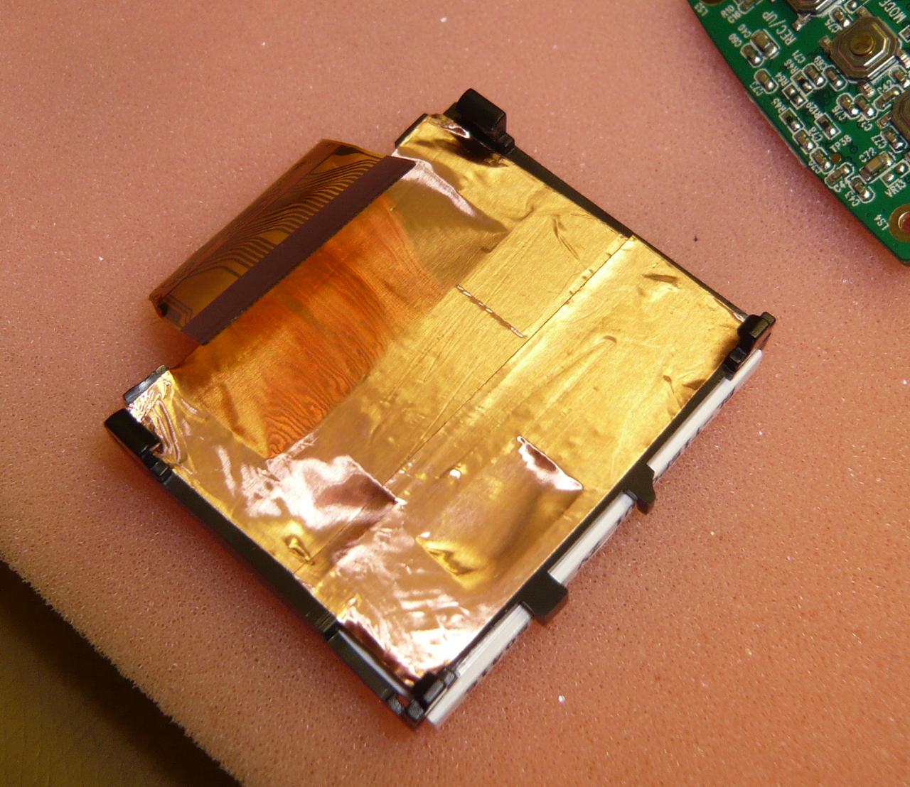
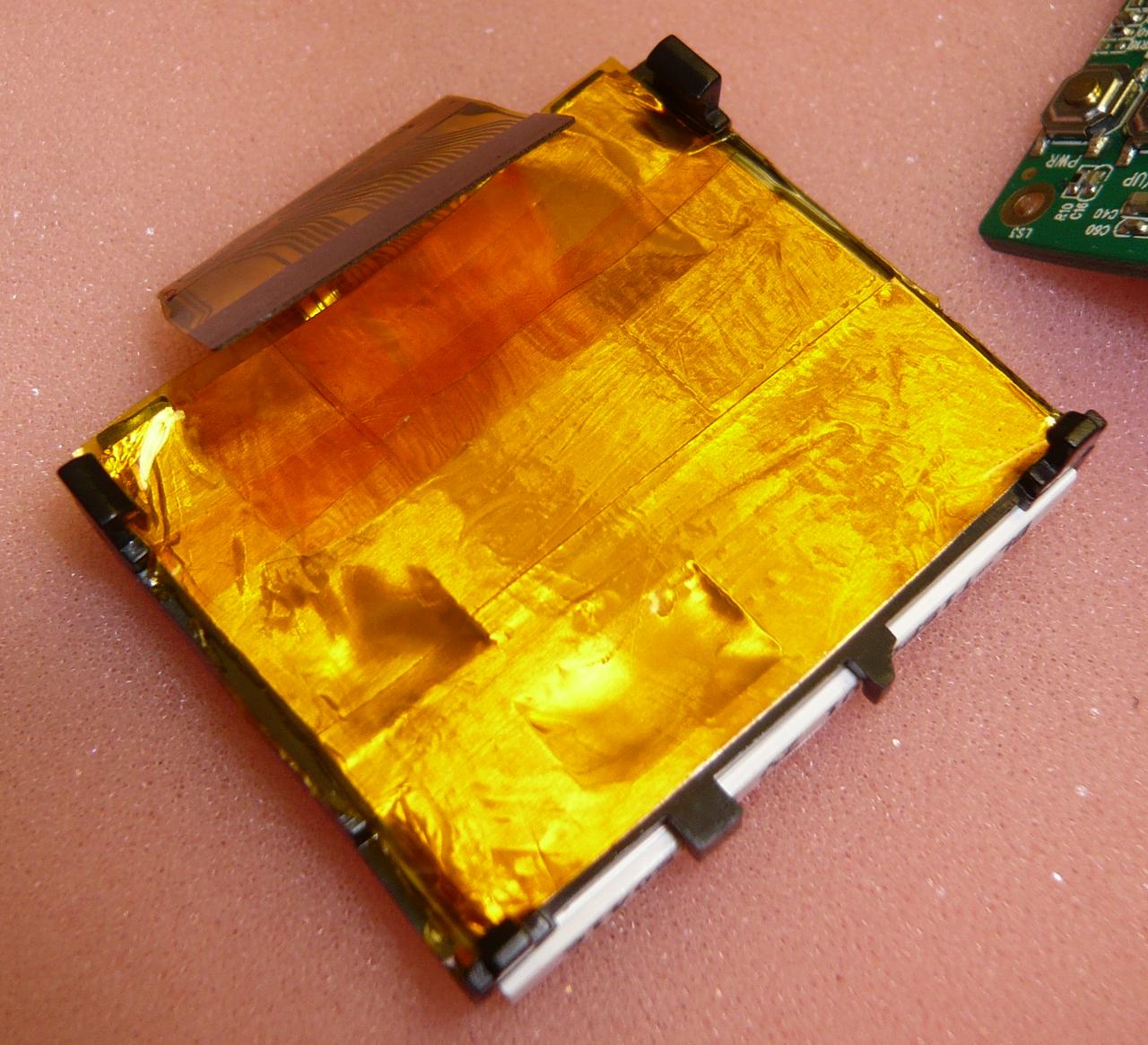
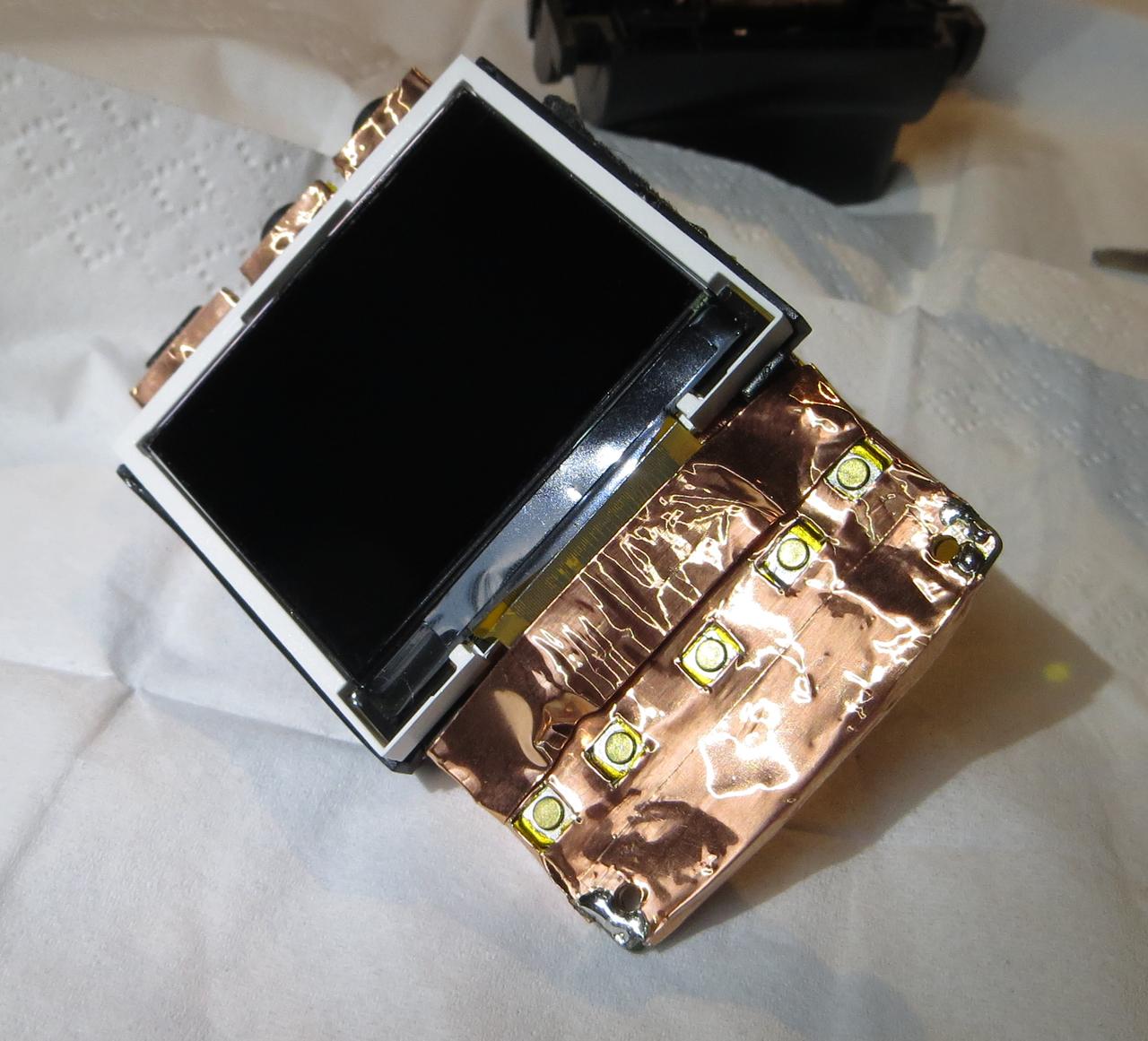
The LCD is also connected with a FFC to the mainboard and hold by the black platic frame clipped on the mainboard. Unclip carefully and lift off the LCD
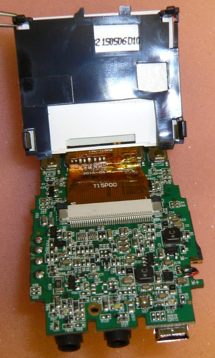
Slide the black clip backwards to disconnect the FFC
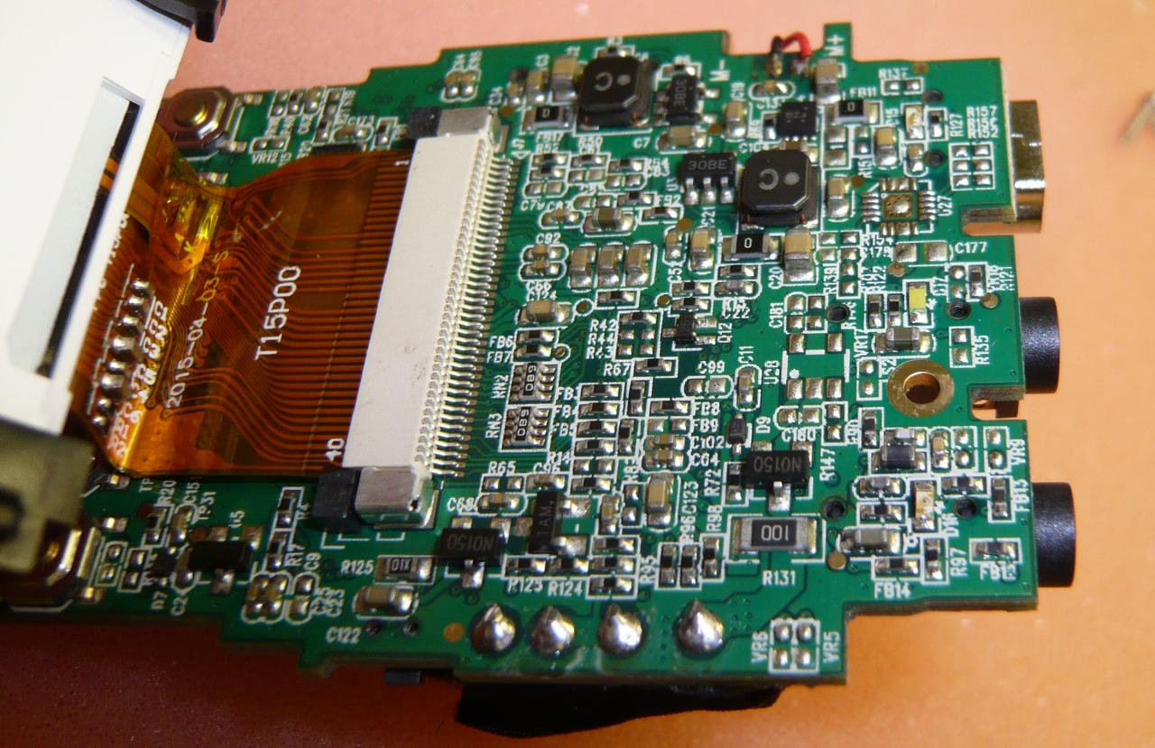
Remove the LCD
Teardown finished!
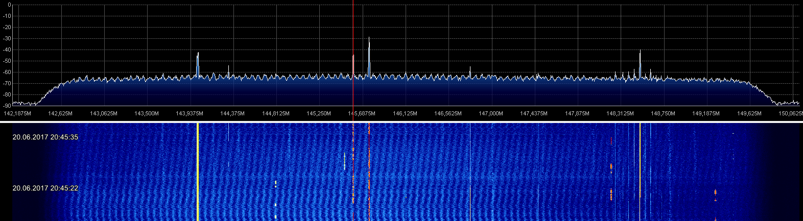
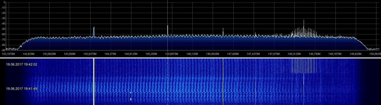
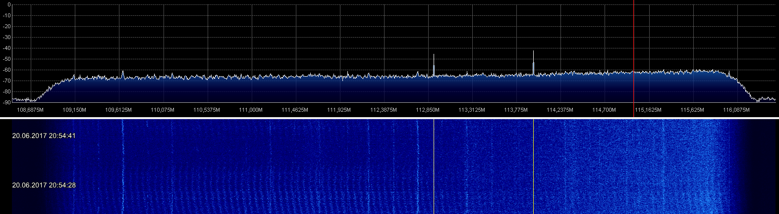
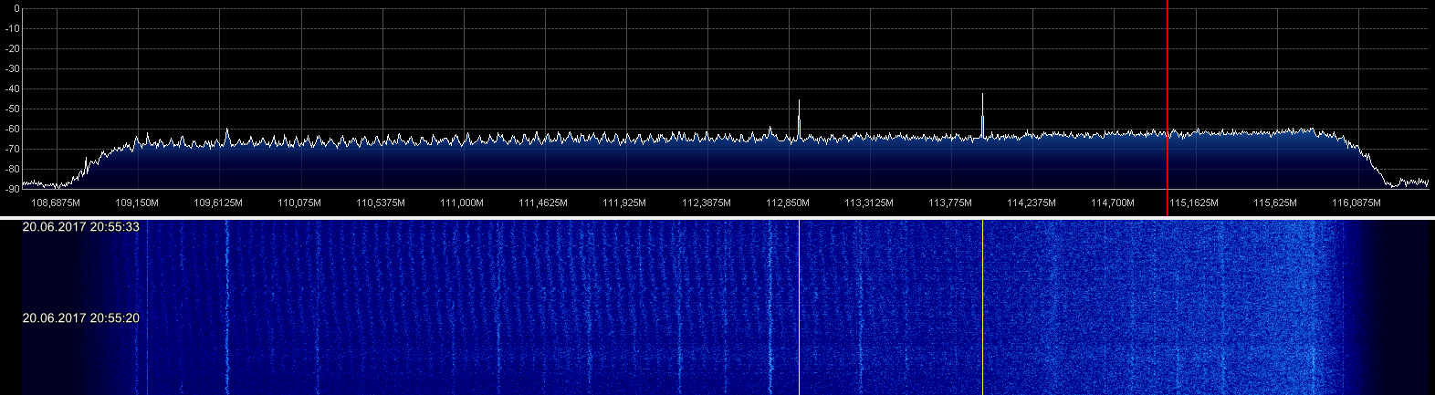
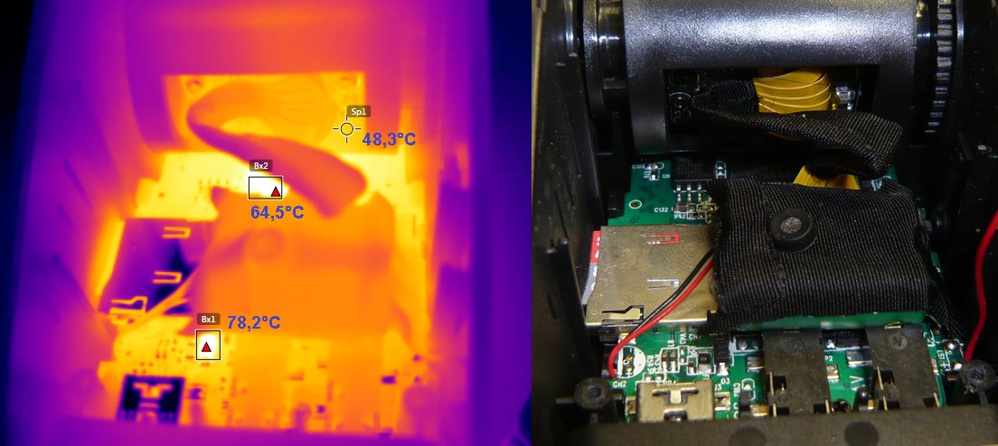
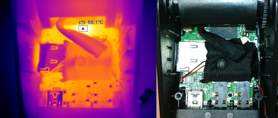
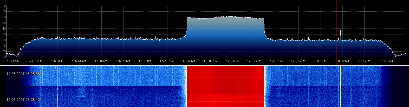
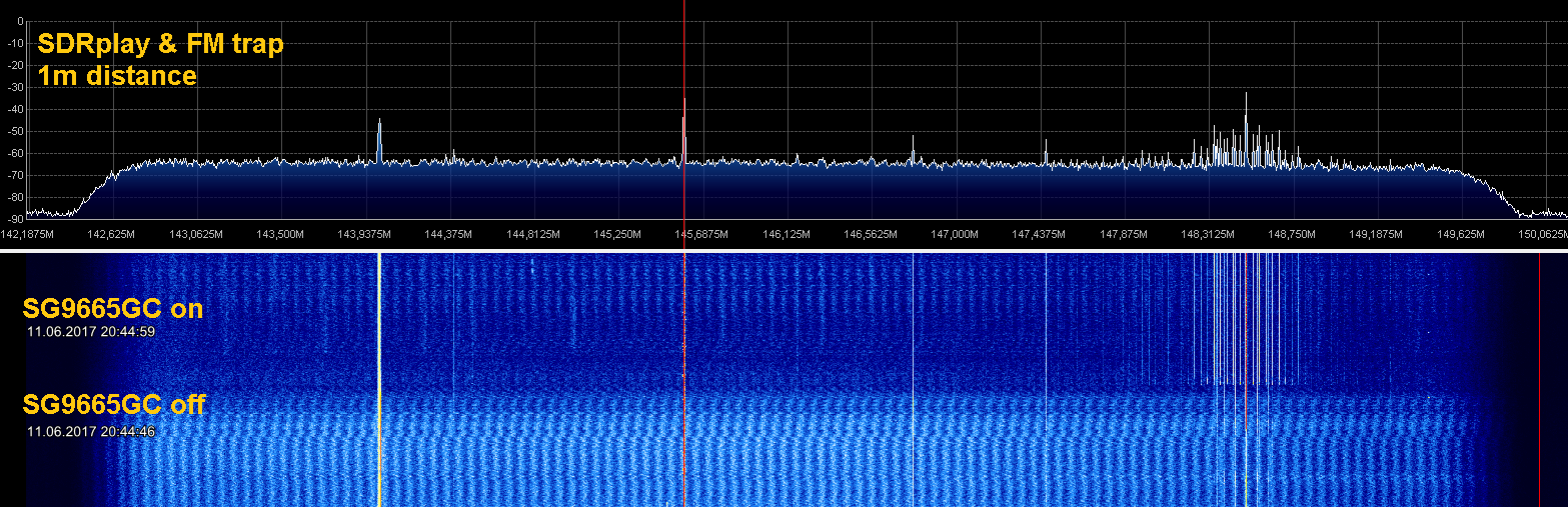
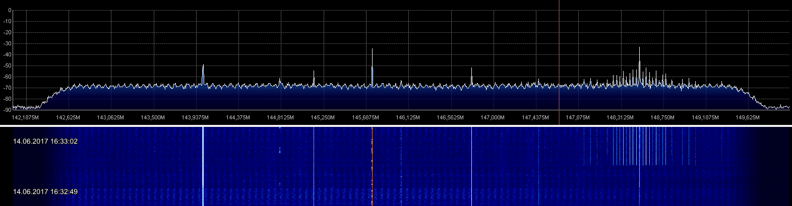
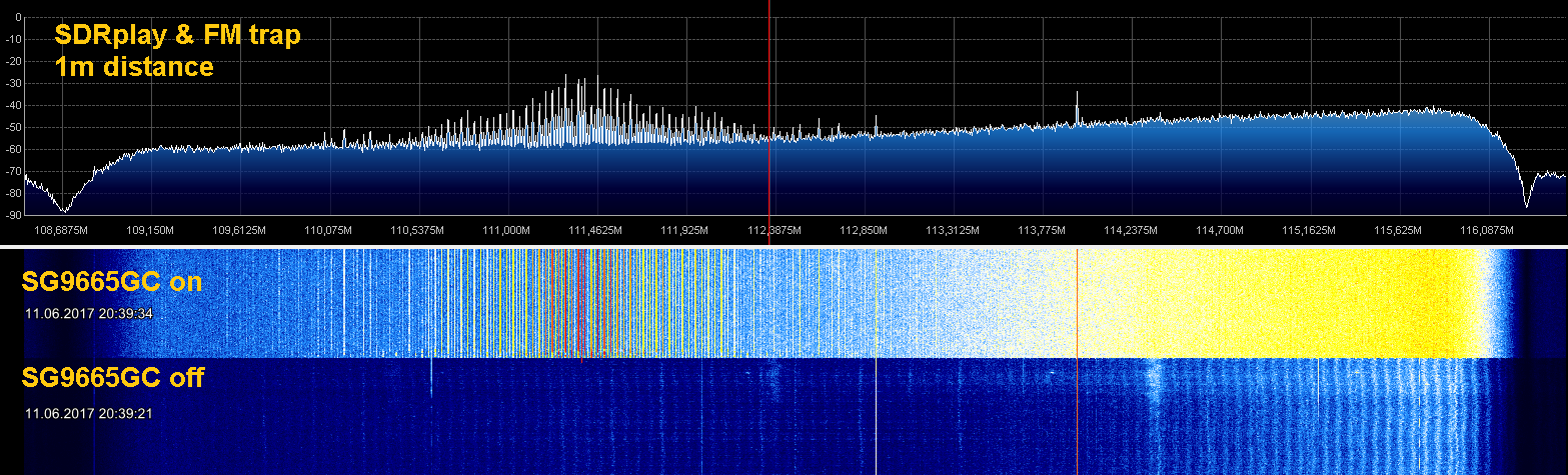
RFI part in the following posts...
Regards
Hex
welcome to everyones favorite segment: Teardown!
Foreword
After swapping my car over a year ago I dind't install the SG9665GC again because back then I had issues with RFI. I could either use amateur-radio and listen to DAB+ radio or record the traffic and listen to music from the USB drive. Normal FM radio was also getting noisy when the SG9665GC was running. Back then the DAB aerial was mounted on the windscreen, approximately 50cm away from the cam. The USB power cable for the cam is DIY made of 2x 0,5mm² litz wire (AWG21 - AWG20) to fit around the windscreen and behind the airbags.
After the last RFI-thread I thought it would be a shame to let the SG9665GC rot in the basement. Because any warranty is long gone I could also do a teardown and some shielding attempts.
Now the SG9665GC is again mounted on the windscreen but the DAB aerial is mounted near the hatch, approximately 2m away from the cam.
Teardown
I couldn't find any teardown of the SG9665GC, so here we go. The Cam is V1.
The case is held together by four screws, two might be covered by labels.
The camera must point upwards a little bit to disassemble, also mind the cable for the speaker.
To take out the sensor/lens assembly remove two screws which hold the adjustment knobs.
Now you can access the main PCB
Remove the tape from the capacitors and mainboard. The PCB is marked with "B40 MB_V21_20150129"
Now you can see the Novatec processor NT96655BG with RAM HXB15H1C160BF (couldn't find a datasheet, probably its 1Gbit) on the right and FLASH 25L3206E (32Mbit) on top. Below there is a battery and a crystal for the RTC and also some pads, probably for a serial interface.
The connector for the FFC (flexible flat cable) towards the sensor/lens assembly is behind the caps
Lift the caps carefully, they are attached to the FFC and connector with adhesive tape
Lift the black clip on the connector upwards to disconnect the FFC. Don't forget to mark the FFC...
Below the FCC the main crystal/oscillator was hidden
Now you can continue with the sensor/lens assembly
The case consists of two plastic part holding together with four clips. The PCB is screwed to the front of the case
The two bigger screws in the middle of the PCB hold the lens assembly, the screws diagonally hold the PCB.
Unscrew the PCB to get out the sensor/lens assembly
As promised the lens and lens holder is made of metal. The lens is glued in with a good amount of glue which does not come of easily (in case you want to adjust the focus).
The sensor PCB is marked with "IMX122_V01 840_SEN 20141230" and contains probably the low noise LDOs (low dropout linear voltage regulator) requiered for the sensor
With the sensor/lens assembly removed you can unscrew the three screws holding the mainboard and remove it
Buttons
And LEDs
The LCD is also connected with a FFC to the mainboard and hold by the black platic frame clipped on the mainboard. Unclip carefully and lift off the LCD
Slide the black clip backwards to disconnect the FFC
Remove the LCD
Teardown finished!
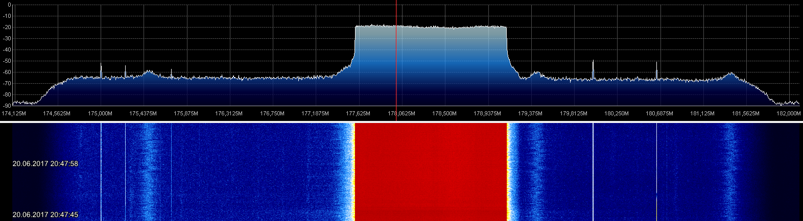
RFI part in the following posts...
Regards
Hex
Last edited:


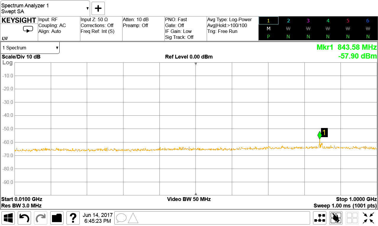

")
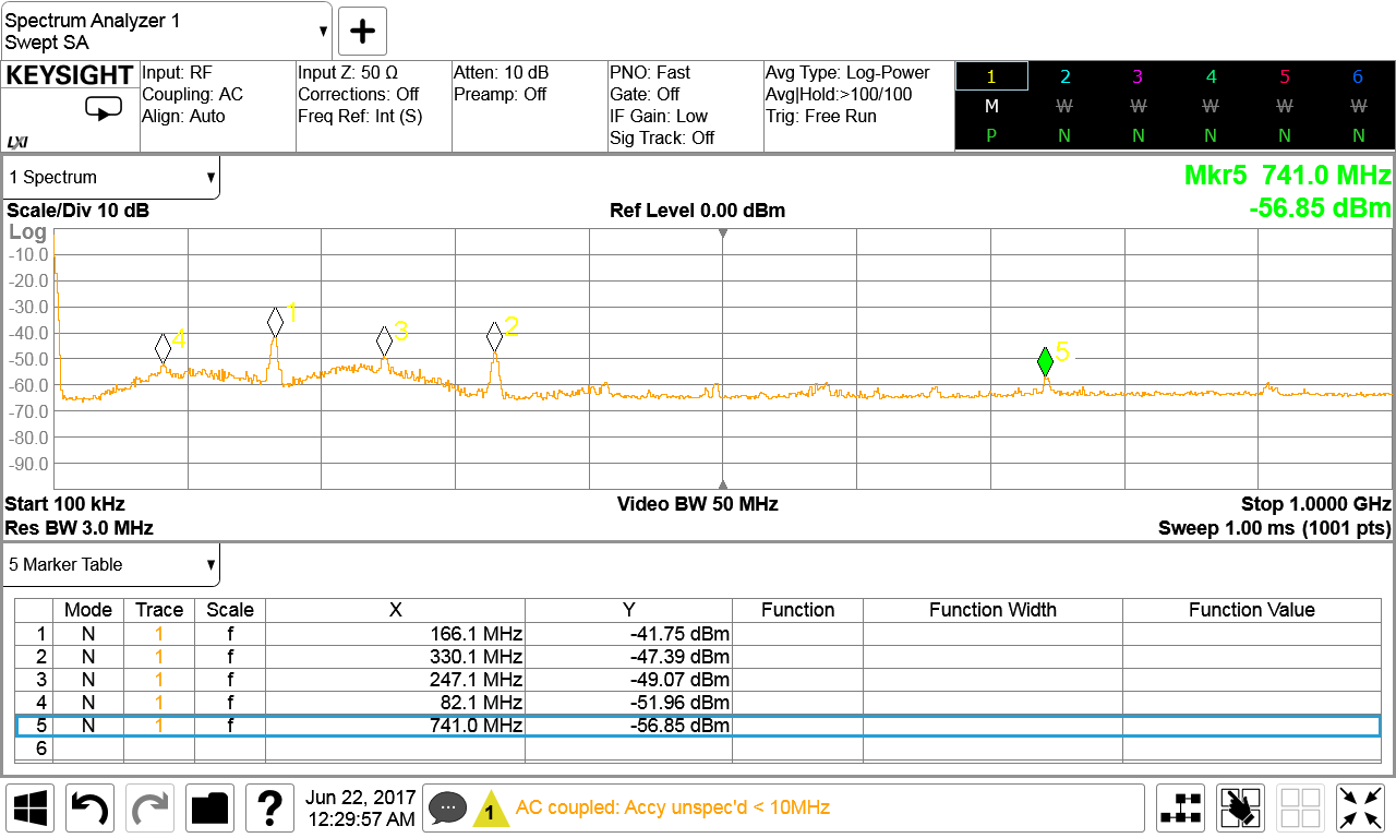
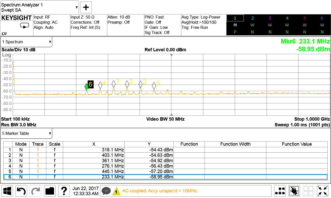
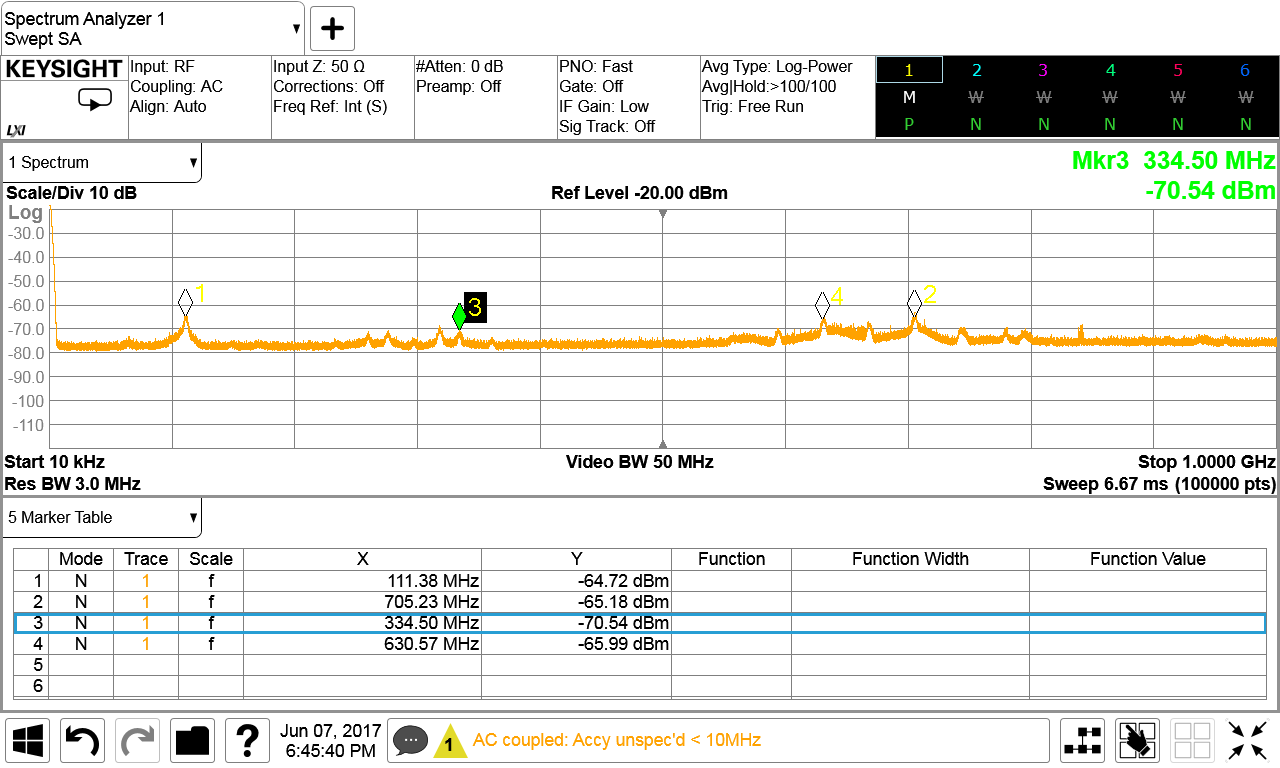
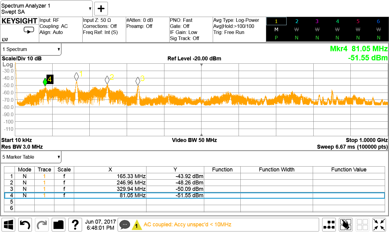
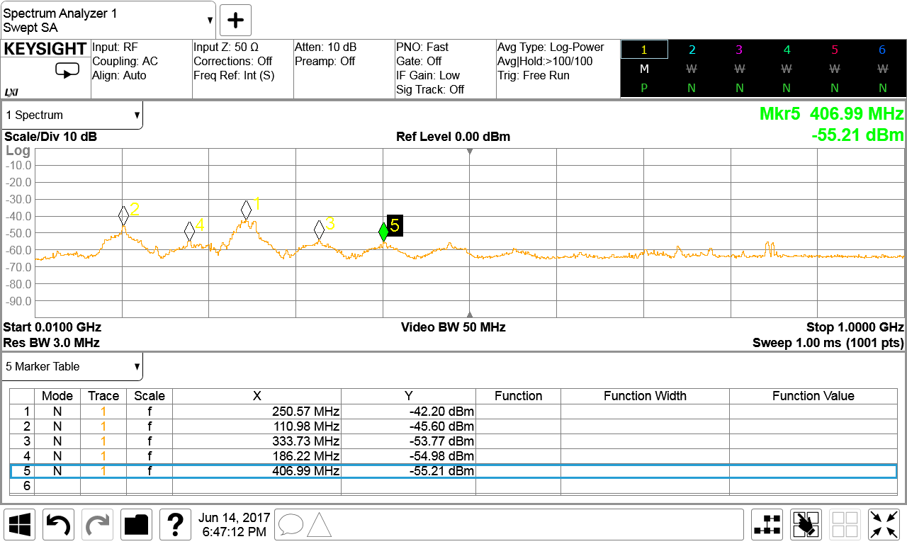
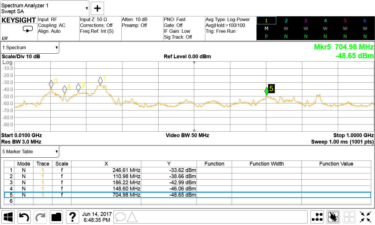
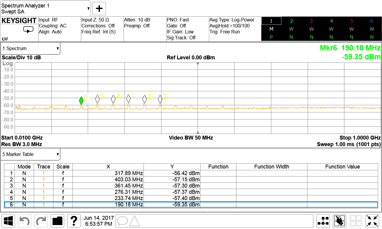
 I don't know if those could be easily shifted to less troublesome frequencies as some of this must be inherent in the workings of the processors etc so that the can manufacturer is stuck with them. Some changes would be welcome though
 ")
 We are doing this to ourselves, and often without any real need
  I fear that until everyone has big problems with it that nothing will change to keep it from happening, and I do worry what those changes will be.
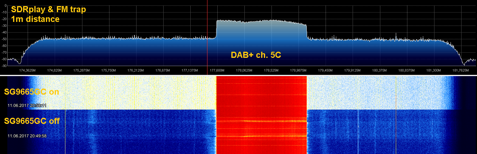


")