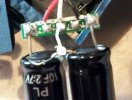
Supercaps / Capacitors installation DIY project and Tests. B40 ( A118 )

dear niko, thank you for sharing this activity and the superb ’surgery’. well done!
inspired by your review elsewhere in this sub forum, I ordered my first dash cam last week (a B40 of course).

reading this thread today aroused my DIY ghouls and I ordered a few 10F Nichicon super caps. :)

i’m toying with a slightly different idea for the supercap implementation, and I will appreciate any comments/suggestions on this -

why not do a hybrid battery-supercap implementation at the 5V power supply end? this gets done externally without disturbing the cam itself.
my ‘candidates’ to retrofit the two 10F supercaps are -

a) any cigarette lighter usb power adaptor, like the one in the B40 review.

b) a 12V to USB hardwired type of box

c) If nothing else, point-to-point soldered male and female USB A sockets and the supercaps.

this way, the battery life might improve slightly and secondly this rig then becomes reusable across different cams.

cheers!
-ootb
 
The problem is that after ignition cutoff the A118 continues to record for about 10 seconds.
It is a bit too long for a supercap.

For example, my G1W stops recording immediatly after ignition cutoff.
 
Size wise capacitor's hold very little when compared to Lipo batteries of the same size.
My first experience with a 10F supercap was to to see how long it could power an LED drawing 10ma. The result was that the voltage and current dropped off fairly quickly and the LED went out about 15 seconds after power was removed. The current for dashcams is many times that and the current demand will not drop proportional to voltage, so the capacitors would have to be hundreds of times larger to do the same. The time and/or the current demand have to be significantly reduced. Time can be reduced in firmware, current demand in hardware. For DIY's, cameras with quick shutdowns under 100ms or so are the only reasonal candidates for capacitor mods. These numbers provided are only speculation at this point. The math needs to be worked out based on the current and shutdown time requirements to better understand the feasibility of such a mod.

Edited: Frankly I still like the idea of removing the battery and disconnecting the charging circuit. Then installing a continuous 5v power wire to this connection.
 
Last edited:
I've been following this thread with interest and have been meaning to post to it for awhile now. As some of you know, as an experiment, I installed external super-caps in a GT680W and to my surprise it worked quite well. Everything functioned perfectly and the camera performed exactly as it did running off the supplied 110mAh battery. It would always properly save all files including the last file. That serendipity lasted about 5 weeks until I started to notice some problems. Occasionally, there would be one, two or three un-openable but apparently full length files on a card and the last file would be smaller than anticipated and also would not open.

As I've said, the camera functioned on the super-caps exactly as it had using batteries. That is to say that after installing the caps, the camera would go through the normal start-up and shutdown procedures. In particular, on shutdown, the camera would launch the logo splash screen, and the shutdown chime would sound. The camera would continue to operate without external power for ten seconds and the last file was always intact. Now, when power is removed, either by turning off the ignition or pulling the mini-B plug from the unit there is no logo screen or shut-down chime, although the LED indicator on the bottom of the camera continues to flash for eight seconds. It is as if the super-caps are still functioning but not at their previous output.

I retired the camera from my vehicle and replaced it with another until I had some time to explore what happened and it wasn't until this week that I've had some time to do a few tests. I've tried going back to the supplied power supply that came with the camera, I've tried different settings such as changing the length of the clips, turning off GPS and disconnecting the module as well as swapping different microSD cards. I've run the camera indoors off a mains powered USB power supply and it will record all files except for the last one, which is still corrupted. The next thing, when I have some time will be to dismantle the camera and check the solder connections, try a fresh set of caps or reinstall a battery.

In any case, I have no clue about why this experiment worked for 5 weeks and doesn't now.
 
Last edited by a moderator:
The fact that you no longer see the logo screen, and the shutdown chime could indicate that the capacitors are not getting a full charge and/or the capacitor voltage is dropping to quickly.

Try the following steps, if you do not have a volt meter skip to step #4:

1) If you have a digital voltage measure the voltage across the capacitors and see if it is close to 5v. Keep in mind that as the charge approaches 5v the rate of voltage increase will slow down. So allow the voltage a few minutes to reach the target. If the voltage is low it could be a bad solder joint on the capacitors or a defective charging circuit.

2) Also measure the voltage across each capacitor. The voltages should be equal around 2.5v. If the voltages are not close to equal, the capacitors are not balanced, or one capacitor is bad or leaking.

3) If the voltages in steps #1 & #2 look OK, monitor the voltage across the capacitors when power is shut down. If the voltage drops off quickly, within a second or so, and charged to 5v in step #1 within a second or so. Then the capacitors are not taking a charge.

4) Try the battery again, if it works then it is the capacitor's.

I have a GT680W being delivered tomorrow, I can make some measurements and compare to yours.
BTW, Since i live in the hot Florida sun, I plan to do this mod also, so thanks for posting your work.
 
@wrdjr20, Thanks for your feedback. Yes, I do have a VOM. In fact, I did the same testing back when I put this project together. Like I've said, when I get a little time I will dismantle the camera and do some testing. The only test I won't be able to try is test each capacitor individually at this point since I soldered a copper bridge between the two caps when I put them together. (see photos from the other thread)
 
I did see the way you mounted the capacitors and assumed that you could measure the voltage at the capacitors without taking the camera apart since they were mounted externally. Measuring between the copper bridge and the positive capacitor lead and between the copper bridge and the negative capacitor lead should provide the two voltages. Looking at the pictures again I see you painted the capacitors, but it looks like you can get measurements with pointed probes between base of the capacitors and the beginning of the insulated wire. Also a pointed probe should be able to also poke though the paint on the copper bridge. If one of the capacitors capacitance is slightly lower then the other, the voltage drop across it will be higher, possibly above the 2.7v max rating, which could lead to failure. Higher voltage differences would indicate a failure.

These are only suggestions based on what I think I am seeing in the pictures. Of course your in a better position to determine the best course of action. Hope this is helpful. Let us know what you find.
 
I've made some voltage tests on the super-capacitors I installed almost 2 months ago in my GT680W with some interesting results.

In keeping with wrdjr20's suggestion I am posting the results on my original thread about the super-cap GT680W mod HERE for anyone who may be interested.
 
Last edited by a moderator:
I'm not an expert, but doesn't the white lead mean there are two cells connected in parallel?
So shouldn't you use two 5.5V caps with the center connected to the white lead for them to charge properly?

cap.JPG
 
I'm not an expert, but doesn't the white lead mean there are two cells connected in parallel?
So shouldn't you use two 5.5V caps with the center connected to the white lead for them to charge properly?

View attachment 6043

i'm no expert either but no i don't think so. the white lead is most likely a test lead so the camera can read how much voltage is actually in the battery (or cap). since the caps are connected in series, they appear electrically as a single 5v device. the original battery only had 2 leads (+ and -) going to the charging board, so it appeared the same to the charging circuit.

my only concern with using caps is losing settings and time/date. wonder if you could somehow add a coin cell or something specifically for keeping settings/rtc...
 
my only concern with using caps is losing settings and time/date. wonder if you could somehow add a coin cell or something specifically for keeping settings/rtc...

Even the dual 5F super-cap module available for the Mobius camera will hold time and date settings for 7-10 days, so assuming you drive your vehicle periodically there should be no need to add a coin cell.
 
Even the dual 5F super-cap module available for the Mobius camera will hold time and date settings for 7-10 days, so assuming you drive your vehicle periodically there should be no need to add a coin cell.
the mobius doesnt have a screen, which is the most power hungry part of any device except maybe the camera sensor itself.

sometimes i do go a week or more without driving my car... could be parked at the airport for a week or 2 while i'm off at training or whatever, or i might work from home for a few weeks and if we go anywhere, we use my wife's van since she can't drive stickshift and it's easier to haul the kids and their stuff. so i'll just put up with the battery. it's been fine in my old f70 which just turned a year old.

I can certainly understand your concerns if you plan to leave the camera sit in an unused vehicle for up to two weeks without being used but what difference does it make if a camera has a screen or not when it is sitting dormant?
 
I can certainly understand your concerns if you plan to leave the camera sit in an unused vehicle for up to two weeks without being used but what difference does it make if a camera has a screen or not when it is sitting dormant?
no difference, but if the screen is on during shutdown (which it is on this camera) it drains the caps that much faster, leaving even less for keeping settings/clock. settings could be kept in nvram so they wouldn't need battery backup but the clock always needs juice - no way around that.
 
no difference, but if the screen is on during shutdown (which it is on this camera) it drains the caps that much faster, leaving even less for keeping settings/clock. settings could be kept in nvram so they wouldn't need battery backup but the clock always needs juice - no way around that.

you're looking at it from the perspective of the battery version, things are handled differently in the capacitor version
 
Back
Top