Trouble wiring VIOFO A119v3. Actually, trouble selecting fuse slot.

Anyway, he suggested to use one of these. If you don't want to click the link then the listing is basically "6 Ways 12V -32V Blade Fuse Box & Distribution Bar Bus Boat Car Kit Marine Holder".
That is a neat solution to adding multiple devices to your accessory circuit, looks a decent device to me.
Fix it in next to the fuse box using some tie wraps.

I was actually thinking of a multiway "cigarette lighter" socket, but this is neater and will take up a lot less space.

Though I still don't get why the 7.5A fuses should be avoided as you said earlier - things like the dashcam should only be using about 1A total. So that'd be 6.5A left? Or is that not how it works? And I don't mean that in a sarcastic manner - that should just illustrate how little I know about electronics that's all so some of my questions will seem stupid.
So as 2 of my devices are dash cams so that'd be 2x 1A each. The other device is only a phone charger.
The issue with the 7.5A fuses is that all the circuits will be built with maybe 10% safety margin, so the more powerful circuits allow you to take more power before you exceed the safety margin, or if you connect the fuse tap the way around I suggest then the bigger fuses allow you to take more power before you blow the fuse. If you used a circuit with a 1A fuse then you would be doubling or tripling the load, which would not be good.

If you have a 7.5A fuse that you know is not actually being used then it is fine to use that, or if you know that only 2A of it is used then it is fine to use it with an extra 2A added, but if 7A is being used by something and you add another 2A of load then there is a safety issue.

The advice not to use 7.5A fuses is only because that reduces the risk of unexpected problems.

So in your case you have 2x 1A dashcams, plus a 4A phone charger, so you need a fuse with 2x1+4 = 6A spare capacity. In other words the car equipment using that fuse must not take more than 1.5A.
Although having read on it says:

If you can make sense of that?

So are we talking about 4A? 3A? 2A? or 2.4A?

I'd be using the USB-C PD slot if that makes a difference?
In reality, your dashcams are going to take more like 0.5A each and your phone charger 1.5A, so you really need a fuse with 2.5A spare capacity.
(You are measuring your dashcams at 5V, and your car is at 12V+, so you can divide your dashcam Amp figures by 12/5, and your phone charger, if you are only using the PD output, it will only be outputting 2A at 9V at most, which is 1.4A, plus add 0.1A for inefficiencies. The 4A claim will be very pessimistic and only occur if you are using all outputs at minimum battery voltage.)

Those Anker chargers are good, I've got a similar PD one.
 
Strange one - I've just been looking through the list of what is what in the fuse box, looking out the A ratings. Anyway I get to radio & see it's marked as F72 20A. I check it against my sheet and F72 is a perm-live fuse.

But my radio is most certainly not perm live. It turns off when I take the key out.

But I then spot on the list of fuses that F69 is marked as radio & instrument cluster at 7.5A. Check against my sheet & F69 is indeed marked as switch-live.

So what's the idea behind two fuses where the radio is listed? Is F72 so that it retains its memory?

If so then why do you need a 20A fuse to retain memory but a 7.5A to power it up? Or is it that it's 27.5A to power it up?

I know we're going a little off on a tangent here but it baffled me.
 
But my radio is most certainly not perm live. It turns off when I take the key out.
Most have permanent power so that they can keep the time, and keep the radio station settings. Not really required with modern technology, but radios do have permanent power.
But I then spot on the list of fuses that F69 is marked as radio & instrument cluster at 7.5A. Check against my sheet & F69 is indeed marked as switch-live.
The radio needs that too, so that it can turn on when you turn the car on, if you had it on before the car turned off, and that is another reason it has a permanent power - so it can remember if it was on or off.
If so then why do you need a 20A fuse to retain memory but a 7.5A to power it up? Or is it that it's 27.5A to power it up?
Because the 7.5A is only used to tell it that the car is turned on, it gets its power from the permanent power, because people like @kamkar have "car radios" that pump out 1000 Watts of bass, so need 12V * 20A = ohh, only 240 Watts = not enough for Kamkars, but enough to power the relay that provides a direct battery feed!
 
This thread seems to be going round in circles
 
Ok so to save you grabbing the link, here: https://www.autogenius.info/ford-mondeo-mk3-fuse-box-diagram/

So I've had a run through to see what I think is suitable for each that also allows room (e.g. can't use F69 even though it may be suitable because F68 is being used & the fuse tap then blocks access to F69). So...

VIOFO - needs 1x perm, 1x switched
Phone Charger - needs 1x switched
Rear cam (Mio) - needs 1x switched
So 1x perm, 3x switched.

So I'm thinking F74 - the perm for the VIOFO (20A, trailer coupling - unused)

3 switched...

F62 - 15A, light switch
F83 - 15A, heated seats (drivers heated seat has gone knackerd this winter just gone anyway & unlucky passenger if that one goes too).
F88 - 15A, daytime running lamps (not sure if they mean fog lights as this car doesn't have DRLs)

Other contenders for switched

F92 - 20A, trailer coupling
F93, 10A, brake lights.

So what you think of using those? I know you've said about loading one fuse up for many but as I say, I'm not comfortable doing that myself. Sure I could pay someone to do ALL of this but if what I'v ejust suggested here is fine enough then I see no need to.

This thread seems to be going round in circles

Apologies for trying to learn something. I know some pick up quicker than others. Maybe I'm slow.
 
So what you think of using those?
Seems a reasonable list, but I would avoid the brake lights, since you might want the camera to continue recording after someone runs into the back of your car and fuses the brake light circuit!

Apologies for trying to learn something. I know some pick up quicker than others. Maybe I'm slow.
You seem to be lacking knowledge and experience rather than being slow!
Don't worry about it, learning is good...
And very very few people would think of my reason for not using the brake lights fuse without asking!
 
Superb, thanks. Makes sense and seems so obvious when someone says it. One of those why didn't I think of that moments.

Anyway, thanks for the help. Looks like I should be good to go. Certainly get the VIOFO & phone charger in. Mio cam in the rear perhaps a little more questionable. Depends on routing it. I saw CraigDIYs install on YouTube & he'll be infinitely more competent than me so I'm not totally sure there. Possibly partly due to having the A229 Pro in the back of my mind - but then I'd have to route it anyway.
 
@Nigel couple things before I get started. This morning I went out & identified where the + was coming in at on the switched.

And side note - I tried detecting anything + when the ignition was in pos1 like Kremmen said and found absolutely nothing or at least not in the suitable fuses I was trying. Pos1 powers the radio. I had to turn it to pos2 where the dash lights up - THEN the switched fuses got power.

Anyway, there's a couple empty slots. One is marked as trailer coupling. As I don't have one then this should be fine.
The other, according to https://knigaproavto.ru/shemy/en/ford/mondeo/477-2000-2007-ford-mondeo-mk3-fuse-box-diagram.html, is actually listed as "not used" with no fuse rating. It does give a reading with the ignition on though - in that it's not perm live, it's switched live.

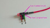
Now as I understand it, the original fuse goes in the bottom slot where the tail leads off to your right with the additional fuse in the top slot.

No problem for something like the VIOFO - as they include this in the kit. Every fuse tap has the additional fuse with it. I need to find where I've put it but purple off the top of my head if that means anything?!

So question is what about when I'm tapping in to those empty slots

1) There is no fuse to put in the bottom slot - as they're empty. So where do you put what will be your device fuse? Bottom or top?

2) In the case of the empty slot for the trailer coupling, it's rated as 20A. Do I need to get myself a 20A fuse and put it in the bottom or am I ok to put some kind of fuse in whatever slot you answer in the last question?

3) In the case of the empty slot that is actually labelled "not used" there is also no fuse rating, obviously, so what do you use?

As I say, the VIOFO comes with its own added fuses so no problem.

The Mio dashcam doesn't & neither does the phone charger - what fuse ratings would you use for these as I would need to buy these seperate. I literally only have a 12v female socket at the moment for those two.
 
#1 your fuse goes in the slot in line with the lead. If you then have the expected power you have inserted the fuse with the correct orientation. If you do not have power, flip the add-a-fuse 180 degrees. If the orientation then becomes awkward put a similar size fuse in the empty slot.. your device power will then go through two fuses but that is no big deal.
#2 use a fuse rated for the device you are using <5 amps typically for a dash cam.
#3 your choice to use whatever size you need ( as per #2) Keep it less than what the manual states for the trailer fuse (20A)
 
5A fuses are good, nearly everything comes with 5A or more rated cable. The fuse purpose is protecting the cable.

If you want to be extra safe 2, 2.5, or 3A fuses would also be good.

Just to clarify Ralf's answer:
2) In the case of the empty slot for the trailer coupling, it's rated as 20A. Do I need to get myself a 20A fuse and put it in the bottom or am I ok to put some kind of fuse in whatever slot you answer in the last question?
You could put a 20A fuse in the bottom slot, but another 5A would also be fine. Depending on which way around you insert the fuse tap, you do or do not need the bottom (original) fuse.
 
Depending on which way around you insert the fuse tap,
Ok for clarification, all fuse taps, providing there is adequate space to do so (and I think I've mapped it out so that this will work) will have the positive leg going in to the positive hole.

Un7grxKl.jpg

Basically where they've marked it up with a red line, that will be inserted in to the hole that is giving a 12v reading, be it switched or perm. The leg they've marked green will be going in to the hole that gives a 0.00v reading.

Not sure which way that makes a difference to what you just said but that's how I'll be wiring it up.

#1 your fuse goes in the slot in line with the lead. If you then have the expected power you have inserted the fuse with the correct orientation. If you do not have power, flip the add-a-fuse 180 degrees. If the orientation then becomes awkward put a similar size fuse in the empty slot.. your device power will then go through two fuses but that is no big deal.
Aware that I may sound like I'm going round in circles here

But did you basically just say try all variations until you find one that works? lol. That's how it reads to me. If that's not what you said then apologies, I've got the wrong end of the stick.
 
Basically where they've marked it up with a red line, that will be inserted in to the hole that is giving a 12v reading, be it switched or perm. The leg they've marked green will be going in to the hole that gives a 0.00v reading.
That is how I expect it to be, although it would be possible to manufacture the fuse tap with the legs connected differently, which is why I suggested you check the continuity within the fuse tap. I've never heard of one being different though.

Not sure which way that makes a difference to what you just said but that's how I'll be wiring it up.
You will not need a bottom fuse for the empty slots if that diagram is correct.

But did you basically just say try all variations until you find one that works? lol. That's how it reads to me. If that's not what you said then apologies, I've got the wrong end of the stick.
What he said is reasonable, but I understand your "confusion", and I'm not going to try and explain it!

If it works without a bottom fuse, which I believe it will if you do as you have just described, then don't worry.
 
Slight development yesterday. Well not really but it turns out I already have a 12v female wired in (differently) to how I remembered.

I bought the car in 2020 & got a wiring kit for my head unit. I wasn't sure how to connect up the steering volume controls so left that part out & connected the rest.
Recently learned how to do it so set to the job yesterday which is when I realised about the wiring.

In my last car I had a guy from an auto electrical shop install a dashcam (the Mio Mivue I have). Instead of piggybacking in to the fuse box, even for the 12v female, he wired it in to the head unit wiring.

Now not wanting to start pulling wires apart because I don't have a clue what I'm doing, when I installed my head unit in to my current car 2 years ago, I left it in place (the 12v female).

When I initially installed my Mio dashcam in to my current car, I did so using one of those hardwire kits off Amazon, piggybacking in to the fuse box, but as previously mentioned - it didn't seem to like the winter temperatures. That's when I switched to using the dashcams own 12v male cable in to the 12v female.
BUT in a cowboy rush, I also left the old wiring in place because when I initially installed it and ran it down inside the A pillar, it took me literally about 45 minutes to an hour to get that damn thing back on so I didn't really want to mess with it again taking the (now unused) wiring out.

So I'm not 100% sure on how the wiring is currently connected up as it's been a couple years since I messed with it and I've forgotten.


However, on the plus side I guess, Kremmen said I should really look for a feed that is ON in ignition pos1 - which the radio is. And the current dashcam connected how it is works perfectly fine. All I need to do is instead of having a load of wiring behind the glovebox is route the cam itself to the rear window as best I can.


So why am I posting that?
Well why would someone install like that - connecting direct in to the head units wiring (so you always have this 12v female connected up) vs just piggybacking direct to the fuse box where you can just simply remove it no problem?
 
No ...... I said find a circuit that only becomes live in ignition position 2

They are the circuits most likely to retain power whilst the starter is cranking

In my experience the radio circuit is temporarily disabled during cranking.
 
No ...... I said find a circuit that only becomes live in ignition position 2

They are the circuits most likely to retain power whilst the starter is cranking

In my experience the radio circuit is temporarily disabled during cranking.
Apologies. I've just re-read. Yes you did.

And yes it does.

The radio was the only thing I noticed that came on in pos1.

Weirdly though, it's been perfectly fine connected to the radio wiring using its own 12v male cable. Granted, I know you didn't say it was a rule that pos1 leads to problems.

Still though, why would someone wire it that way? Are there benefits to it vs just piggybacking one of the fuses in the fuse box?
 
What frequently happens is :

Key turned to ignition pos 1, dashcam starts to boot
Key then turned to ignition position 2, dashcam continues to boot
Key turned to sprung loaded ignition position 3 and starter motor fires .......... at this time power is cut and the dashcam senses the loss of power and starts to shutdown.

Power is restored as soon as you release the key but the shutdown procedure has started.

I hope that makes sense
Yeah I got it when you said.

I just asked why someone would wire it in how that guy did. I was curious that's all & I don't fancy the funny looks of going to him & saying hey you remember me from about 3 years ago? To which he wont.
So thought I'd ask here. I don't know, I'm an electrical idiot but just because I don't understand why it's done that way doesn't mean that there isn't a very good reason why it was.


But what you said made me think -

I said the dashcam didn't like it in the winter. Maybe winter had nothing to do with it. Maybe i'd piggybacked in to the wrong fuse that suffered the problem that you mentioned & that's why it froze.
 
In my last car I had a guy from an auto electrical shop install a dashcam (the Mio Mivue I have). Instead of piggybacking in to the fuse box, even for the 12v female, he wired it in to the head unit wiring.
I just asked why someone would wire it in how that guy did.
He was probably a head unit installer, and that was all he understood!

Maybe he had never heard of a fuse-tap, since all cars come with head unit power cables pre-installed, so fuse-taps are never required.

Don't assume that a professional installer will know more than you do. He will have more experience, but knowledge is only a maybe, for that you need an expert. Note however that experts do not always have experience!
 
Back
Top