A Beginner’s Guide to Installing the SG9663DC Hardwired for the 2013 Prius V (Gen 3 Prius) - Basics apply to any hard wire vehicle install

Striker

Member
Joined
Jul 16, 2018
Messages
32
Reaction score
37
Country
Canada
Dash Cam
SG9663DC
1532287832474.png

Please read through everything before you begin. Do not be afraid to ask for help in these forums (this is a great community).

i. Preamble:

I am not responsible for injuries or damages to yourself or others, your vehicle or your property (or if your 2013 Prius V’s fuse box, airbags, you or your world spontaneously burst into flames). My experiences with wiring is limited, having taken Electronics back in grade 9 high school, but I have tinkered with my PC, set up a SteamLink box, and burned eproms for Atari cartridges. And now I’ve successfully tinkered wiring a dash cam with a Prius V. That said, if you are uncomfortable in tinkering with your vehicle’s electronics, seek a professional to complete your hard wired dash cam installation.

I could not find a detailed guide to install a dual dash cam system for a Prius V, and no easy complete (more or less) guide for beginners, so I compiled all the background info that I have learned and added my own experiences while completing this project. Hopefully it will be useful to those new to installing dash cams.

Also, I am definitely no expert, so I am willing to accept guidance, help, constructive criticism, etc. I will try to credit info that I have obtained from other sources. Most of the photos/images are mine, except for a few stock images of the dash cam found online. Here we go... The basics here should apply to all cars.

ii. Parts of this Guide:

Part I. Order the SG9663DC & and the hard wire kit
Part II. Placing the Two Camera Bases and GPS
Part III. Prepare to Wire the Fuse Box
Part IV. Set Up the SGDCHW (the Hard-Wire Kit)
Part V. Connect the Fuses
Part VI. Connecting and Testing the Dash Cams
Part VII. Making It All Look Professional
Part VIII. Damn It Grommet
Part IX. Conclusion
Part X. Credits
Part XI. This space reserved [firmware/settings?] - TBA
Part XII. This space reserved [videos?] - TBA


Part I. Order the SG9663DC (don’t forget the SD card, I ordered the 128 GB card)

1532288231108.png1532288272629.png
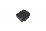
Front cam unit and rear cam

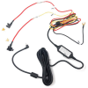
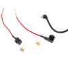
and the hard wire kit Street Guardian SGDCHW SG9663DC Hardwire Kit with Mini ATO Low Profile fuses (the 2013 Prius V uses these).
1532288373358.png1532288488748.png
Hard wire kit, also showing fuse taps and 5A fuses

Patiently wait for the dash cam and hard wire kit to arrive.
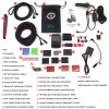
Whats in the box.jpg
Items included in the original kit

Then...
 
Last edited:
Part II. Placing the Two Camera Bases and GPS

1. Front Camera Base
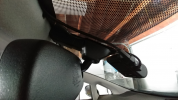
Choose a place near the base of the front mirror that does not obstruct your view. Also make sure there is enough space to press the camera buttons and attach the wires. I chose here:

1532331586588.png

Clean the glass with the provided wipes or use water and a paper towel.
After you have planned where to place the camera, carefully attach the camera base to the glass. Apply pressure for two minutes. Do not attach the camera for 20 minutes (refer to the guide in the box).

2. Rear Camera Base
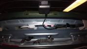
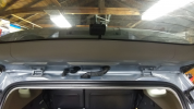
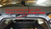
I placed the base in-between the first and second defogger wires.

1532331613378.png
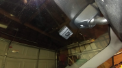
View from rear with hatchback opened

Make sure you leave enough room for the USB wire to be attached. Later, I had to use a 90 degree USB attachment from the rear camera here since its base is very close to the car siding material. Again, hold the base for 2 minutes and don’t place the rear camera on the base for at least 20 minutes.

3. GPS attachment
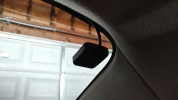
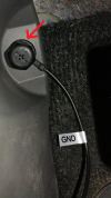
I used the supplied window attachment and placed it in the upper right passenger side (North American). After 2 minutes, I hid the wires under the roof trim here.

1532331640833.png

While you are waiting for the sticky pads of the bases to cure to the windows, you can do the next step, which is more difficult.
 
Part III. Prepare to Wire the Fuse Box

1. Find the fuse box
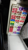
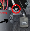
Since you are hard-wiring, you have to find a fuse box in your vehicle to attach the hard wire kit. The Prius V has two (one inside near the parking brake pedal and one under the right side of the hood); I recommend using the interior one near the parking brake pedal.

1532331799074.png

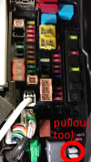
2. Obtain the Fuse Pullout Tool
You still need to access the external fuse box under the hood to get the fuse pullout tool.
(see p.412 in owners manual).
1532331832759.png

3. Find where to attach the wires of the hard-wire kit
Now go back to the internal fuse box. Make yourself comfortable, because this fuse box is in a very awkward position. I almost pulled a back muscle trying to get to it. Also, I had to use the torch/flash on my cell phone to see the fuses.

4. Circuit and Electrical Knowledge - A Multimeter is Useful for Finding Where the Live Connections Are...
If you just want to install the fuses skip the multimeter testing, but I recommend you use a multimeter as good practise when dealing with wiring and electronics.

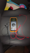
If you want to learn about which fuses are live or not, use a multimeter, set V to 20, and test the fuses. Any multimeter will do. Search the forums or ask for options if you need one.

1532331924068.png

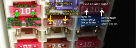
The right side of a single fuse (in the interior Prius V fuse box) is live (attached directly to the battery), and the left side of a fuse attaches to the appliances/utilities, for example, lights, electronics, cigar lighter.

1532331984912.png

When testing if a fuse is live or not, touch the red wire to the right side of the fuse and the black wire to ground (any metal part of the car like a screw near the fuse box. If the fuse is live, the multimeter should read ~12V. If no power is being received by a fuse or empty slot, the multimeter will read ~0V.

5. Recommended fuse slots to use
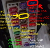
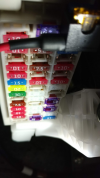
Using a multimeter and the fuse info starting on page 417 of the Prius V owner’s manual, I decided to use the 15A cigar lighter fuse on the top right of the fuse box for my ACC connector and an empty slot in the live middle fuse column. Make note of the 15A fuse location, as it will be pulled and inserted into the empty slot of the ACC (red wire) fuse tap connector later.

1532332055080.png

You are looking for one permanent (always on/live) fuse and one accessory switched power fuse (off when engine is off).
 
Part IV. Set Up the SGDCHW (the Hard-Wire Kit)

1. Set the switch on the small black box to 12V
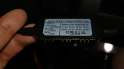
Looking at your hard wire kit, set the switch on the small black box to 12V, which is the second setting from the left when the label is face up. This will shut off the dash cam in parking mode when it drains to a certain level to keep your Prius battery safe.


1532332164264.png
Second setting from the left is 12V


2. Set up the fuse taps and wire connectors
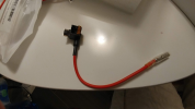
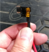
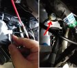
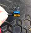
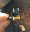
To set up the fuse taps and wire connectors in the SGDCHW kit, attach the included yellow 5A Mini ATO Low Profile fuses, one to each wire. Place the yellow 5A fuse in the fuse tap slot closest to the wire for both wires.

1532332231758.png
1532332266220.png
Fuse tap close up

3. Attach the end fuse connectors of the kit to the red (ACC) and yellow (Battery +) wire. It doesn’t matter which connector and wire you attach right now. (The 15A cigar lighter fuse from the Prius V fuse box will be attached to the ACC (red wire) fuse connector later.)

1532332290502.png
ACC (red wire) attached to the fuse tap connector (note blue 15A cigar lighter fuse and yellow 5A fuse already attached)

1532332319941.png
Battery+ (yellow wire) attached to the fuse tap connector, with yellow 5A fuse already attached
 
Last edited:
Part V. Connect the Fuses

I recommend using the following slots and/or fuses for wiring:

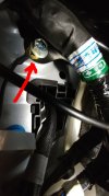
1. Ground (black wire): Attach to any free metal screw near the fuse box. Always ground the circuit first for safety. A good, safe ground source would be a metal screw attached to a metal plate behind the kick panel. Initially, I had chosen the screw that held the kick panel in place; that was not a good choice.

a) Pull up long door sill panel; this will allow the kick panel to be removed.
01 02 20180723_102831.jpg

b) Unscrew the plastic screw cover of the kick panel, near the fuse box (that was my initial choice for a ground connector), then remove the kick panel.
03 04 20180723_102904 -s.jpg

c) Look for a good ground source behind the kick panel.
05 07 20180723_103019 -s.jpg
The metal screw in the second image will do.

d) Use a size 12 wrench to loose the bolt of the screw. Insert the ground connector and tighten the bolt. Give the ground a light pull to ensure the connection is good.
08 09 20180723_103703 -s.jpg

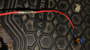
2. ACC fuse tap (red wire from hard wire kit): Attach to the cigar lighter fuse. First, pull the blue 15A fuse from the Prius fuse box and insert it into the empty slot of the fuse tap connector next to the yellow 5A fuse. Then insert the fuse tap connector (with the fuses facing upwards and the 15A in front of the 5A, the wire should be sticking out on the left) back into the fuse box where you removed the 15A fuse from.

1532332450036.png
15A fuse inserted into ACC fuse tap connector

1532332479069.png
ACC fuse tap connector inserted into fuse box

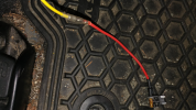
3. Battery+ fuse tap connector (yellow wire from hard wire kit): Insert into an empty slot middle row. This wire is always live and will work when your dash cam is in parking mode. Make sure the 5A fuse is in the back slot of the fuse tap connector closer to the wire, and that the wire is facing to the left when inserting the fuse tap connector.

1532332508282.png
Battery+ fuse tap connector

1532332529858.png
Battery+ fuse tap connector inserted into fuse box

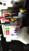
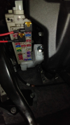
4. With the fuse tap connections are completed, the fuse box should look something like this...
(This is not really a step, just a celebration that this part is done!)

1532332562331.png
Hooray!

5. After you have completed all the ground and fuse steps, use cable zip ties to tidy up all the loose wires and close up the kick panel and door sill panel.
1532475062964.png
 
Last edited:
Part VI. Connecting and Testing the Dash Cams

Now you can plug in power to the cameras and GPS to make sure it all works, otherwise you could be removing all the wiring later if something is defective.

Watch Street Guardian’s video of how to apply the EVA foam to the base of the front web cam
to avoid vibrations on your video. Make sure you take note of your serial number before you apply the foam.

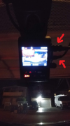
Attach the cameras to the bases and attach all the wires (see manual for what goes where). I had to use the 6m rear camera wire for my final setup, as the 3m one was too short. I found that the dash cam didn’t go on the first time until I started my Prius, and then the camera system started up. (It may start automatically for you after a few seconds.)

1532332695919.png
Plug in the power to the front camera USB slot. Note: added GPS 90º extension later

If wires are not too messy (you could temporarily tape the wires up with green painters tape to avoid a dangerous, dangling mess) take your Prius out to test how the camera works. When you get back, I recommend upgrading your firmware to the most recent one supporting the hardwired setup. At the time of writing, the link to the most recent beta is here. (The latest public release for the SG9663DC is here under the firmware tab.) Then check to see if your are satisfied with all the camera settings. Defaults are fine for most.

1532641004545.png
Cables tidied up and plugged in. Note: use cord clips as needed

1532641089449.png
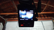
Booting up!

1532641131012.png
It lives!!
 
Last edited:
Part VII. Making It All Look Professional...

...or not... comments/suggestions are welcomed.

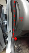
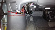
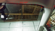
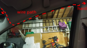
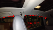
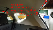
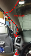
For the fuse box area, I used zip-ties to wrap up the excess wire lengths and carefully stuffed it in the side of the vehicle, away from the parking brake pedal for safety. For both the front and rear camera wires, I just stuffed the wires in the sidings, carefully trying to avoid the airbags. I was able to do this just by using the supplied vehicle trim tool supplied with the SG9663DC. Take special care not to crimp or fold the USB wires or the connection may be damaged.

1532332858590.png
From front to fuse box #1

1532332879367.png
From front to fuse box #2

1532332898230.png
From front to fuse box #3

1532332915907.png
From front to fuse box #4

21E Front cam to fuse box 20180721_222906 -s.jpg
From front to fuse box #5; fuse box area

1532332959547.png
From front to GPS & rear cam #1

1532332987512.png
From front to rear cam #2

1532333004398.png
From front to rear cam #3

1532333020280.png
From front to rear cam #4

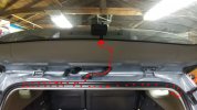
20180725_224330 rear cam completed path.jpg
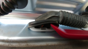
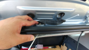
From front to rear cam #5 From front to rear cam #5 - Edit: Wire has been carefully looped to avoid crimping under the nearby headlining. Feeding the wire through the grommet (rubber hose) was moderately difficult. I used a zip tie strap taped with quality packing tape to the wire, covered the tape and wire with soap, and guided it through. See Part VIII Damn It Grommet for more details.

Alternately, you could obtain access to the Toyota online subscription based service repair manual for $20/2 days. The service repair manual goes into great detail about how to remove the headlining. This info is not really necessary for this type of project.
 
Last edited:
Part VIII. Damn It Grommet

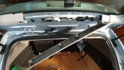
My first time installing a wire through a grommet was moderately difficult, so I added a part dedicated to this.

1532600065078.png
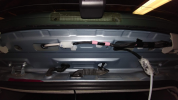
1. Remove back door centre garnish. Insert the prying tool and pull.


1532600094005.png
2. Access both sides of the wider grommet. The wire will be fished through in steps, because I had cheap, lousy electrical tape from the dollar store. I later switched to a good quality packing tape and soap for lubrication of the wire, so I may have been able to fish everything through in just one step, however, it’s better to be safe than sorry.
1532600124970.png


1532600164729.png
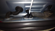
3. Fish a larger zip tie through the base of the now opened grommet to the loose wire. Attach the zip tie to the wire and guide/pull it above the headlining to the base of the grommet. (Note I zip tied the base of the USB connector so that the wire would not slip out, instead of using tape.)


1532600206451.png
4. Remove the first zip tie. Run a second zip tie through the top of the grommet to its base and attach it to the wire cable, using a good quality tape. Cover the area you will pass through the grommet with a lubricant like liquid soap. This will allow the usb connector and cable wire to pass easily through the grommet.


1532600304289.png
5. Run the wire from the grommet to the rear dash cam.


1532600336638.png
6. Replace the grommet and back door centre garnish. Arrange the headlining if it has been displaced, along with any other loose panels.
 
Last edited:
Part IX. Conclusion

This was quite an education and workout (the garage was hot, even at night) for me as an electrical DIY project with my Prius V. I took care to make sure what I was doing was safe and that I knew that what I was experimenting with had a high success rate. The most difficult part (aside from all the researching) was completing the wiring to the rear camera. I was tempted to get a professional to do it, but I decided to finish what I had started.

Everything in my vehicle is still working. Nothing has caught on fire and the battery has not died. My cell phone can still do a full rapid charge with the cigar lighter as a power source.

The dash cam is working great so far; I’m very happy with it. It’s terrific in the day; at night during the right conditions I can read the plates if a vehicle is right in front and travelling slowly. That’s to be expected for 1080p recording for what I consider to be an upper mid-tier dash cam.

The hard-wire kit is still undergoing firmware updates at this time of writing, but it functions well in parking mode at 1fps for 10 minutes. I’m getting to the point where I want to let it operate on its own, but I still check for firmware updates. Hopefully the WiFi features will be updates as well.

I may update this guide if necessary. If you are new to installing anything in your vehicle and what to give it a try, best wishes and stay safe. Hopefully you will learn something like I did and enjoy the results as well.

Edit: Many thanks to the forum members in the credits for their help with improving this guide and my dash cam setup. I have relocated the ground and rewired the rear cable, switching the ends and passing it through the grommet.

Take care and stay healthy!
Striker
 
Last edited:
Part X. Credits

Special thanks and acknowledgement to the following, organized by date (Note: some links are commercial websites):

how to get wire's through grommets and door boots by ghostlyrich, 2013-08-24

Easiest way to hardwire a Dashcam into car fusebox by Pixel Pirate, 2014-05-08

Piggy-back fuseholders – a right way and a wrong way by eugel, 2014-09-25
https://dashcamtalk.com/forum/threads/piggy-back-fuseholders-a-right-way-and-a-wrong-way.7524/

Easy Method to Hardwire Any Dashcam, No Experience Required by al_x, 2014-10-11
https://dashcamtalk.com/forum/threa...wire-any-dashcam-no-experience-required.7712/

Installing a 2 Channel Dash Camera by CANADA DASHCAM.COM, 2015-02-10

DashCam Install How To: Running Camera wiring into rear hatch by Lockdown Security, 2015-02-21

How to Install a Rear Camera on a SUV/Hatchback by blackboxmycar, 2016-04-25
https://www.blackboxmycar.ca/blogs/news/158376583-how-to-install-a-rear-camera-on-a-suv-hatchback

How to tap into your cars fuse box safely and cleanly by Five Star Car Stereo, 2016-12-09

SG9663DC install on a Tacoma by venezian, 2017-11-09
https://dashcamtalk.com/forum/threads/sg9663dc-install-on-a-tacoma.31557/

How to Install a Dash Cam – Installation Guide by Blackboxmycar, retrieved 2018-07-19
https://www.blackboxmycar.ca/pages/how-to-install

How to Hardwire a Dash Cam by Blackboxmycar, retrieved 2018-07-19
https://www.blackboxmycar.ca/pages/how-to-hardwire-a-dash-cam

Advanced Dashcam Installation by The Dashcam Store, retrieved 2018-07-19
https://www.thedashcamstore.com/advanced-dashcam-installation/

Dash Cam Frequently Asked Questions (FAQ) by The Dashcam Store, retrieved 2018-07-19
https://www.thedashcamstore.com/dash-cam-frequently-asked-questions-faq/#101_q12

[Removing the driver’s kick panel]
No Squirt, retrieved 2018-07-23
https://techno-fandom.org/~hobbit/cars/nosquirt/

Thanks to jokiin for advice to improve the safety and looks of the install.

Thanks to kamkar1, Nigel, & Gibson99 for their help and advice.
 
Last edited:
Part XI. This space reserved [firmware/settings?] - TBA
 
Last edited:
Part XII. This space reserved [videos & extras?] - TBA
 
Last edited:
have a few comments but let me know if you're not finished yet and I'll delete this post and wait until you have
 
Hi jokiin, I'm done for now. Please let me know what you think; I'm open to suggestions and edits; thanks!
 
ok a couple of comments, for the record I think you've documented this very well but a couple of small details which would step it up a notch and some things to look out for

your earth point is potentially a problem, look behind or around the fuse box and you should see a factory grounding point where other circuits from the fuse box are terminated, it will be to a bare metal area, generally behind the kick panel, anthing where you also have a plastic trim piece or dash part or often insulated for NVH reasons, it could even work ok initially but can build up a bit of resistance over time and start getting flaky

1532332425197.png


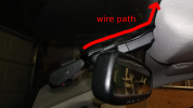
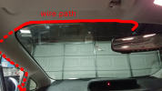
The rear camera cable you've installed the wrong way around, the right angle end is meant to go at the camera end, likewise there's a right angle adapter for the GPS so that the cables can be routed straight up to keep things neater

1532332602628.png


At the tailgate end we generally run the cable through the factory grommets and bring it out just above the camera, it's neater and no chance of fouling a cable

1532333038580.png

Overall you've done well, not criticising at all, just a few little things you could do to step it up a notch

We're working on some firmware improvements now so if you haven't already make sure you register your extended warranty so that you get the notifications once they're ready
 
Thanks for the comments! They are very much appreciated! I'll look into the issues and try to make the fixes. Cheers!
 
Sorry for the newbie questions! Is this a good ground connection under the kick panel? I looks like a lot of wires terminate here. I've unscrewed the bolt so it was loose, but the ground connector only went this far in. Should I not worry about forcing the hard wire kit ground connector in, or just remove the entire bolt? I'm afraid I'll screw up and lose the original connection. I worry too much!
new ground 20180723_104834 -s.jpg
 
That look like a good spot.
I have the same predicament wit the GND wire for my 12 V expansion to the back of my car, i am just using one of the bolts that hold my rear seat in place.
 
If you have a spare M6 nut then the circled bolt would be a really easy one to use - just put your ground connection on top of the existing nut and add another nut on top.
Make sure you don't affect the functioning of the controls though.
1532375917036.png

Can't see your last photo well enough to judge.
 
Sorry for the newbie questions! Is this a good ground connection under the kick panel? I looks like a lot of wires terminate here. I've unscrewed the bolt so it was loose, but the ground connector only went this far in. Should I not worry about forcing the hard wire kit ground connector in, or just remove the entire bolt? I'm afraid I'll screw up and lose the original connection. I worry too much!
View attachment 40281
as pictured it's fine, just make sure to tighten the bolt similar to how it was before (most stuff under the dash doesn't need to be super tight except the obvious stuff like the pedals and steering column). after you snug it down, give the wire a small tug to make sure it doesn't fall out, and you'll be fine.
 
Back
Top