DIY programmable delay shutdown circuit

Sweet. Thanks for posting the images. I like the fact that you're using different colored wires so you can differentiate them. What gauge wire are you using for this rig?
 
whatever I had in my junk wire drawer :) That's really what it came down to in terms of color and splice connections. It was a rough install that was supposed to be cleaned up with solder and heatshrink, but then, life happened.

I use 18 and 20 ga for nearly everything low-current on automotive stuff. Heavier things like inverter or amp power, I'll go as low as 4ga. But with this you're talking very low current. If I were switching 5V at the relay, and had to make long runs to the various points for the cameras, I'd have to go thicker to reduce voltage drop. That's the upside to using 12V right up to the camera location.
 
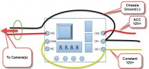
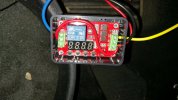
erkme73, your diagram looks a little different than your photo or did you just use different colors? I've righted your photo to make it easier to compare the two.

2015-07-24_0-08-20 modded.jpg


20150724_140513.jpg
 
The colors don't match, but the wiring is the same. At the time of the install, I thought the coloring nomenclature was red = constant, and yellow = ACC. Obviously that's reversed. But, I'm not OCD enough to go back and rewire it. The schematic I modified is the correct color scheme.
 
No worries. It all makes perfect sense. I'm getting ready to pull the trigger on all of this stuff. I just checked and I only have 16 gauge red and black wire in my garage. Do you think that's too thick, especially for the connections that have two cables?
 
You should be fine. If they're too thick to get into the terminal, you can trim some strands or solder them... Or crimp them together outside of the terminal screws.
 
Okay, so I have a bit of a dilemma. Ever since I saw erkme73's video showing all of the cool lights on the timer I really don't want to cover up the electronics. :)

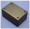
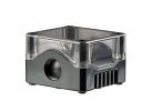
I found two cases that'll work with the timer. One is 3.2" x 2.2" x 1.1" and is a simple, no frills black case, but it will require me to trim the corners of the PCB slightly–probably with a Dremmel. The second is larger at 3.15" x 2.85" x 2", is thicker and better built, and has a clear cover (so you can see the timer innards without opening it), and it doesn't require any PCB modifications.

Plus, I may be able to drill (4) holes in the cover strategically positioned above the push buttons on the PCB so I can insert a paper clip to make timer adjustments without having to open the unit up. But at $17, it's over twice the price of the simple black case. And if I'm going to purchase the more expensive clear covered case, I need a good place to mount the box–which is still alluding me. Any ideas?

BTW, if I do go with the cheaper case are there any issue with using a Dremmel to remove a .25" quarter circle from each PCB corner? This is required to clear the case posts, which are bigger and closer to the case edge than erkeme73's Radio Shack case.
 
Last edited:
Here are the two boxes I found. Actually, both seem to be pretty good quality, but the clear cover case option (right) already has (2) 20mm knock out holes for the wiring, which is a nice time-saver.
1594bk.jpgip67-1hole-blk-clear_400px.jpg

IP67-enclosures_400px.jpg
 
Okay, I just pulled the trigger on my custom Mini 0806 12V Relay Cycle Timer Project. I also decided to spring for the full options package, which includes a Bulgin clear top polycarbonate case, a Siemen cable gland, and (4) adhesive PCB mounts, all of which cost more than the timer itself.

When everything arrives I'll document the install in a new thread, just in case anyone else wants to attempt this mod. Thanks erkme73. I'll likely be in the doghouse for a few weeks over this. :)
 
...I also decided to spring for the full options package, which includes ... a Siemen cable gland...

Uh, that's kinda gross. Was that one to keep Mrs. RM happy?
 
Earlier today, I had lunch with one of my best friends, who happens to be a mechanic with his own auto repair shop. I was telling him about my timer project and he said he's pretty sure my 2012 CR-V has a battery saver feature built into it. Basically, when the electrical system senses that something has been left on, like interior lights, headlights, etc., it will automatically shut down the entire electrical system, except the built-in alarm to prevent the battery from being drained. He said that system might not work is if the amperage for the device is so small that it does't trigger an automatic shutdown.

erkme73, I suspect your Toyota has something similar. How did you get around the automatic shutdown feature or is the mini 0806's amperage to small to trigger the system? Also, where are you pulling 12V constant from? Thanks!
 
Neither the '15 Highlander nor my 07' Tundra have this feature. I know, because in both vehicles, I've accidentally left something on long enough to absolutely kill the battery (to the point where nothing comes on and the starter solenoid won't even click).

ETA: if you find that there is a shut-down circuit, you could always attached directly to the battery for your constant power source. Albeit, it would be more difficult, as you'd have to punch through the firewall... But it could be done.​

As for the 12V constant, I tapped off of an always-on fuse. I don't recall which one, but something that stays constant hot - like maybe the power seats? Both accessory and constant are pulled from the fuse block under the dash.
 
Thanks. I need to do some more research on this. It could deb that Honda only has that protection circuit built into things it know a driver might leave on like interior lights, headlights, etc.
 
Hi,

Thread is from last year but hopefully you're still listening!
I've just hardwired a pair of dashcams with a fuse tap on an ACC-on fuse, and a 12v to 5v step down with two usb outputs like this: https://www.amazon.co.uk/gp/B00GXXFBC0
However I'm quite tempted to wire up something like this so I can keep it on for a set period of time after taking the key out. I just haven't completely pictured the circuit in my head and am confused about one thing (or maybe more things I just don't know about!)

What I think I know:
The wire from the always-on fuse tap goes in to the DC+ input and then the COM in series
The wire from the ACC-on fuse tap goes in to CH1 input
The NO goes out to the step down converter (using the red wire as per the amazon picture)
The DC- goes out to the chassis

What I don't know:
Where does the ground (black wire) from the step down converter, that is currently wired to the chassis, go? Does it stay where it is or does it need to come back to the relay?
I'm sure this is obvious but my feeble mind can't quite imagine the circuit here

Much thanks

p.s. Also, which order do I have to cut the wires to defuse it before it explodes?
 
@erkme73 I just came across this post, want to say a big thanks for the effort taken to explain everything, its something I might now attempt when/if I get time, it’ll be nice to pre set the off time once power has been cut to the DVR

@RavenManic also a big thanks for your contribution to this post
 
one guy, an engineer completely re-wrote the manual (in real English) along with examples of how and when to use specific programs. He emailed me a copy of his manual, along with specific instructions on which mode I needed, an how to set it up. I've attached the manual.
That manual's a big improvement, wish I'd read it before playing with the one I just bought.
Still not easy to work out what the modes do at a glance. I've made up a table, might be helpful. I hope the terminology is clear.
There are probably lots of uses for this with dashcams (crude timelapse for example.)
There is a 5V version that might suit some purposes better than the 12V one.

TimerModes.jpg

Note that mode 10 is the only one where holding CH1 high works differently to a momentary high pulse.
Also modes 8 and 18 do not finish in the On state which you might have expected.

If anyone's thinking of experimenting with one of these, some tips:
For testing, you don't need to hook up an output device. The top blue LED lights when the relay is active. The relay also has a fairly loud click.
The CH1 (trigger) input doesn't need a pull down resistor (though it wouldn't be bad to include one in a final circuit.)
You could hook up a switch between CH1 and DC+, but it's easier and just as effective to have a short, stiff piece of wire screwed into CH1. Tap it against the DC+ socket's screw when you want to trigger the circuit.
 
Many thanks to @erkme73 & @RavenManiac for this post & your contributions. Have a G1W-CB dashcam mounted in my newly acquired '16 plate Yeti. Found that if I wired it to my Acc circuit, the cam will boot OK when I insert the key, but a second or so later, when I spin the starter, the voltage drop on the Acc circuit causes the cam to switch off again. The cam does NOT then restart once the engine has fired up. (I think this is because the power-off and subsequent power-on are too close to each other for the cam to register?) I then tried wiring the cam into a permanently on 12v feed (12v socket fuse) and this allows the cam to carry on running through the engine start up. However, I subsequently forgot to manually power the cam off after a run the other day and, after a few days of not using the Yeti, I came out to a virtually flat battery (which was brand new at the end of July!) So a relay is the way to go I think. Ordered this one off EBay for £3.45 (put an offer in!) - it comes with a pre-fitted project box so seems like a good deal. However, for the life of me, I couldn't work out the chinese wiring instructions shown in the listing. Your guide and comments above have made this impending job so much more straight-forward; it is much appreciated. I think I'm going to set my relay up to allow the cam to keep recording for up to 8 hours after I leave the vehicle, as most damage to previous vehicles I have owned has been done whilst I left them parked. (Nobody ever leaves a note these days!) Will let you know how I get on once it arrives and it is fitted!
 
Looks like for function 10, max T1 timer is 9999 seconds or a little over two hours. Is it possible to go over that?
 
Thread starter Similar threads Forum Replies Date
RavenManiac Mini 0806 45
E Mini 0806 1
Back
Top