DIY programmable delay shutdown circuit

Sorry for the delayed responses. I'm watching this tread but apparently it got buried.

Truthfully, this (the one I linked to in the OP) was the only timed relay I tried. It had great reviews, and stellar community support. In fact, one guy, an engineer completely re-wrote the manual (in real English) along with examples of how and when to use specific programs. He emailed me a copy of his manual, along with specific instructions on which mode I needed, an how to set it up. I've attached the manual.

As far as hooking it up, it's very straight forward. The manual will really help explain it. If you're hung up on cosmetics, I really can't recommend what to use. My Radio Shack project box was the perfect size - it's just the screw holes/pegs had to be removed to get it to fit. Unless you plan on adjusting it regularly, or want to prominently display it on your dash (ill-advised in our post-9/11 boogieman hysteria culture), it'll be just fine even if it isn't neat and tidy.

Russel is the name of the reviewer (in the Amazon reviews) who offered to guide me through the programming stage. He suggested to use Mode 10 - which worked exactly as intended. I've literally set these one time (1 hour for each vehicle) and haven't gone back to make any changes.

What's great is that you can tie in other things that you want to remain on after the key has been removed. For example, your stereo, a cigarette lighter outlet, radar detector (mine has GPS in it, so I prefer it stay on during short stops), etc.

Don't over-think it. The only challenge will be what to use at the other end of the circuit, where you drop the 12V to 5V for the cameras. As I originally posted, the cheap voltage regulators work great. They provide 3A worth of power (though only .5A is required) and are small enough to put inline between the 12V supply coming from the timed relay and the micro USB cable - and covered in heat shrink tubing. That makes for a neat and tidy installation, with each camera having its own dedicated power supply as close to the camera as possible.
 

Attachments

  • Timer_Manual_2015_05_04.pdf
    442.5 KB · Views: 82
Wow! Thanks for your post and the manual. That's a big help. I think this is likely the route I'll go since it's a tested solution that seems to be working great for you, and in two vehicles no less. Since it'll be out of site I'm sure the OCD in me can live with the cosmetic issues. The biggest problem I'm facing is where to put it. Everything is so compacted in today's modern cars and just about every space is used.

The other thing I want to do, which I haven't really made clear in my other posts is I'm trying to compartmentalize the individual components so that if a part fails it can be easily replaced. For example, I previously installed an 0806 hardwire kit, which was a rather involved process. If or when that component fails I'll have to remove the whole apparatus, including the cabling that runs from the fusebox, up the A-pillar, and across the windshield headliner to the dash cam.

With the setup I'm building each component, regardless of what it is, can be easily replaced. If the USB power charger goes bad, simply plug a new one into the cigarette lighter socket. No need to replace the cabling since it detaches from the power supply. I'll want to build the timer into my setup the same way. The good news is I'm assuming the screws are where you clamp down your power cables, which makes the process even easier since there doesn't appear to be any soldering involved.

But I do have a question. I understand why the timer would have positive and negative leads (i.e Service Voltage side, I'm assuming), but why does the load side show that as well? Shouldn't that just be the positive lead from the fuse box to the COM post and then the remaining positive lead to the camera? BTW, which post do you have it on in your Mode 10 setup–NO or NC?

[Update]
And so you'll know, this quest for the ultimate power setup, preferable one that is EMI protected, is to address a high-pitched noise that worked it's way into all of my recordings, which ultimately may have been a defective camera. It's funny how you start out to solve one problem and move on to something totally different, as in a timed dash cam. :)
 
2015-07-24_0-08-20.jpg

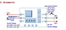
Borrowing from the manual, the left side represents the output 12v + going to the cameras. I am switching the positive. Thus, I have constant 12V+ applied to the common terminal, and the switched 12V+ coming off of the normally open (NO). If the relay is off/not powered, the relay contact is open, and the cameras get no power. Further, there is minimal parasitic load from the relay board (other than the IC that's running the clock, the relay coil is off).

The drawing above shows the constant hooked up to the NO terminal, and the camera to the common, but the inverse (they way I have it) will work too.

Since the cameras need both 12V+ and ground (-), I run a two-wire (red and black) lead from the relay box up to the camera locations. Rather than hunting for a ground at each camera, I tie the ground for the camera to the same ground terminal (DC-) as the service voltage side of the relay (right side of the schematic above).

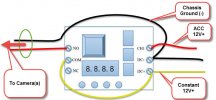
So, you'll apply a chassis ground to the DC- terminal, and a 12+ (constant) to the DC+. Then you tie your ACC 12V+ (coming from any fuse that gets powered when your key is in the ON/ACC position) to the CH1 terminal. That's the "trigger" input.

So long as 12V+ is seen at CH1, the relay remains energized, sending power to the cameras via the NO terminal on the left. Once the ACC power drops from CH1 (i.e. you remove your key), the timer countdown begins. While it's counting down, the relay stays energized, keeping the cameras on. As soon as the timer expires, the relay releases, the circuit opens, the cameras go out, and the board goes into standby mode.

In summary, the output (load) side of the timer circuit is dealing only with 12V+. COM has 12+ constant (and you can just make a small jumper from that terminal to the DC+ terminal on the service voltage side of the board), and the NO has the camera (+) attached.

Make sense?
 
Makes perfect sense. Thank you. You probably saved me hours of time and frustration trying to figure that out on my own.
 
BTW, I take it you're using fuse taps for power. What size fuses are you using for this setup?
 
I ended up 'modifying' the schematic to better show how mine is set up:
2015-07-24_0-08-20 modded.jpg

I tied into the existing cigarette lighter/power point fuse (15A) on the load side. I didn't add another fuse. Keep in mind that I need the extra capacity to handle not just the four cameras, but all the other gear. If you are going to power multiple devices, then you'll have to size your fuse for the combined load - which leaves little protection for devices that will fry with a lower current rating. If you're overly concerned, I would put a fuse in-line at each camera power regulator that is sized for, say 700ma.
 
It's not OCD. It's CDO... You have to sort the letters properly...
 
I edited my post - that AZ listing is for the RS part - same PN and everything. Looks like someone cleared out their online inventory and is now selling it at 3x the price on Amazon.
 
Going down for the evening... Have fun researching and building ;)
 
*watching* I'm interested in this as well.
 
Okay, I think I've found a project box that'll fit the timer circuit board. This has a plastic PCB holder, which you can mount the PCB board to with double sided foam tape or with standoff screws. According to amazon.com the circuit board is 2.59" x 1.57" x .67". Sadly, this enclosure is too shallow for you to use the top.

Small Project Enclosure by New Age Enclosures
Maximum PCB: 2.9" x 1.88" x .538"
http://www.newageenclosures.com/cart.php?m=product_detail&p=62&c=3

[Update]
I found another case on eBay that looks like it'll work. It has a clear cover and seems to be well built. The size of the case is 3.35" x 2.28" x 1.3" and it has mounting tabs. Plus, it looks like there's enough height for the PCB and its components so you should be able to actually use the cover. :)
https://www.ebay.com/itm/131499743610
A Unibox 118 might work too, but I can't find a distributor:
http://www.uniboxinfo.com/images/s100/Pn118sh.pdf
 
Last edited:
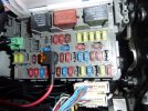
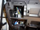
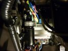
I like the second one I found, but for me I'm still having a hard time trying to figure out where I can mount it. The only place that looks like it might work is to velcro the project box to the three long white tubes in the last photo, which are simply there to protect the cables leading into the fusebox.

Plus the PCB will be forward facing so I can easily modify the settings, if needed. And, accessing this area is relatively easy since that section of the dashboard pulls off by hand. The only issue may be the screws holding the cover in place, but I suppose I could replace those with thumbscrews to make it easier.

P1050082.jpeg P1050093.jpeg P1050092.jpeg P1050081.jpeg P1050091.jpeg
 
Last edited:
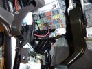
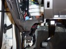
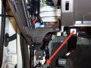
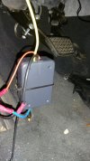
Right here.. under the kickplate. That's where I put mine. I just wire tied it to the wiring looms that were already there to keep it from flopping around (thought he kickplate keeps it firmly in place).

2015-07-24_13-46-58.jpg
 
Yes, I suppose that could work. Thanks. Anyway you can take a photo of yours without a lot of trouble?
 
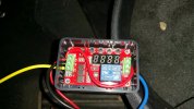
Took some doing, but kiddos are down for a nap and had a chance to snip some wire ties... Messy truck. Obviously, I DON'T have OCD. I have the opposite problem.


20150724_140447.jpg 20150724_140513.jpg
 
Thread starter Similar threads Forum Replies Date
RavenManiac Mini 0806 45
E Mini 0806 1
Back
Top