LTO (Lithium Titanate Oxide) – The Ultimate Battery for Dash-Cam parking mode (DIY)

@EricSan , Lately, I mostly use 4S/184Wh LTO Battery which works flawlessly, never had any issues with 7S/322Wh either, but I am thinking to reconfigure it to 6S/276Wh with the newest high efficient compact size auto back/boost charger and without any converters, for a 12V system, in a much smaller box.
The temperature outside isn't that hot yet, I wouldn't consider it hot until I see 95°F consistently.

On Ecoflow,
I don't think it's a shorted cell that will cause the PS to die completely and create a lot of smoke and smell.
The problem is somewhere else.
Which output? AC or DC, at what rate?
Does it really discharge PS?
Can you re-charge it back?

I believe Ecoflow has an internal fan and overheat protection, so at worst it would shut down due to heat, and resume working as it cools down.
Is it still under warranty? I would try ecoflow support.
 
Last edited:
Yeah, still under warranty, so I need to give them a call. It stopped functioning after a week of 95-97 or so. It does has an internal fan. I thought it was also supposed to not charge/discharge when too hot/cold as well. When its turned on with nothing plugged in, it shows a power draw of 22w to 44w, so the battery doesn't last long at all. It charged from dead flat to 100% in about 10 mins when it should be closer to 60-80mins. I've just been using the 5v USB output and charging via the XT60 plug, no other outputs are active. Just wondering if you ran into any temp related issues so far...
No, no issues due to heating, with LTO, but outside temps here are around ±85°F and not very sunny so far.
Last year I was running N150 PS at otside temps up to ±100°F with no issues, either for PS or Mini2.

The issue as you described is not easily logically explainable, I do not see how heat could cause that.
LFP cells are usually rated to 140°F/60°C, and are the limiting factor, electronic components can work at higher temps.
 
Thanks for some additional details. Glad to hear you haven’t experienced any temp related surprise issues so far.. Tech support has a protocol that I am following: 1) firmware update, followed by 2) State of Charge Recalibration. The recal is performed by three successive full charge/full discharge cycles. I’m part way through that process now, still showing a phantom 34w DC power draw with nothing connected. Perhaps something downstream from the batteries fried as the first charge cycle took about an hour which is pretty usual from an AC cord. Charge cycle yesterday took only 5-10 mins.
 
Hopefully the protocol helps.

This 34 W discharge, if it is real, must turn into heat somewhere.
If not under the warranty, I would suggest to opening PS and using an infrared temperature "gun" to try to find any hot spots.
 
Yeah, that’s a fair amount of heat that should be easy to find, even by touch.

App shows the fluctuating wattage draw (anywhere from 12 to 44w - and way high for that outlet) is coming from the USB-A circuit. My guess is that it’s a cooked 5v voltage regulator because it doesn’t output consistent or correct voltage. USB-C circuit puts out good voltage and current, as does the AC outlet, and the 12v socket. Battery holds a charge so long as it is turned off, so it looks like it is also fine. Have to finish the 3x charge/discharge cycle, which seems to be working, and give them a call back.

If it dies again after warranty service, I’ll build your 4S LTO circuit. Temp range is wider and I can tailor the USB output voltage to my needs for a long cable run to the camera.
 
While my River2 is being repaired (mailed it back today), I am planning to start accumulating parts to build my own LTO battery pack. There is large appeal in being able to service a more simple device on my own. Though I've found some variability in the specs, the LTO batteries seem to function well up to 60c or so. I've been watching your videos (great stuff!) and looking at your parts list and I see a few differences between the 4S build in your video and your parts list. The most obvious difference is the DC-DC bucking converter.

Your video for the 4S LTO shows an adjustable Yipin Hexha DC-DC converter that is in what looks like a potted aluminum case. To me, this looks like a great implementation as the potting is likely to keep any single component (like the shottky diode that each of these devices has) from overheating due to greater thermal mass and more surface radiating area. But your parts list links to a naked XL6009-based board.

So, my first question is why did you abandon the potted converter in favor of the naked board in your parts list? To me, the potted device in your build video seems to be superior to the naked one, but perhaps I'm missing something in the behavior of these units.

It seems that Drok makes a similar potted and adjustable DC converter (they're likely all exactly the same, just with different company logos stenciled on them):
https://www.amazon.com/gp/B00C0KL1OM
A second question: Most of these DC-DC converters specify that the input voltage needs to be 3v higher than the output voltage. So, if I target a 5.5v output level, I need an 8.5v input level. The specs on the Toshiba LTO cells that you linked indicates a minimum voltage of 1.5v and a nominal voltage of 2.3v each. With 4 cells in series, that's 6.0v minimum and 9.2v nominal. So, somewhere between nominal and minimum voltage as the batteries get depleted, voltage seems highly likely to drop below 8.5v, at which point, I'm guessing the DC converter won't be able to maintain its 5.5v output level for the camera. Has this created any problem with your LTO setup as the batteries become depleted? Might it be better to build a 5S configuration to keep the depleted voltage level higher? Or am I missing some other detail related to the output voltage curve as the batteries run down that makes this irrelevant?
 
Last edited:
This 34 W discharge, if it is real, must turn into heat somewhere.
Nope, not real, it's a phantom draw that produces no internal heat and does not draw from the battery. The batteries still hold a full charge and charge/discharge properly. It just messes with the BMS display/calculations, tricking the unit into thinking the batteries are being depleted when they are not. The unit is not capable of delivering power to the USB-A ports. All other outputs (USB-C, 12v utility output, and AC outlets) still work well.
 
While my River2 is being repaired (mailed it back today), I am planning to start accumulating parts to build my own LTO battery pack. There is large appeal in being able to service a more simple device on my own. Though I've found some variability in the specs, the LTO batteries seem to function well up to 60c or so. I've been watching your videos (great stuff!) and looking at your parts list and I see a few differences between the 4S build in your video and your parts list. The most obvious difference is the DC-DC bucking converter.

Your video for the 4S LTO shows an adjustable Yipin Hexha DC-DC converter that is in what looks like a potted aluminum case. To me, this looks like a great implementation as the potting is likely to keep any single component (like the shottky diode that each of these devices has) from overheating due to greater thermal mass and more surface radiating area. But your parts list links to a naked XL6009-based board.

So, my first question is why did you abandon the potted converter in favor of the naked board in your parts list? To me, the potted device in your build video seems to be superior to the naked one, but perhaps I'm missing something in the behavior of these units.

It seems that Drok makes a similar potted and adjustable DC converter (they're likely all exactly the same, just with different company logos stenciled on them):
https://www.amazon.com/gp/B00C0KL1OM
A second question: Most of these DC-DC converters specify that the input voltage needs to be 3v higher than the output voltage. So, if I target a 5.5v output level, I need an 8.5v input level. The specs on the Toshiba LTO cells that you linked indicates a minimum voltage of 1.5v and a nominal voltage of 2.3v each. With 4 cells in series, that's 6.0v minimum and 9.2v nominal. So, somewhere between nominal and minimum voltage as the batteries get depleted, voltage seems highly likely to drop below 8.5v, at which point, I'm guessing the DC converter won't be able to maintain its 5.5v output level for the camera. Has this created any problem with your LTO setup as the batteries become depleted? Might it be better to build a 5S configuration to keep the depleted voltage level higher? Or am I missing some other detail related to the output voltage curve as the batteries run down that makes this irrelevant?
Great questions!!
As you noted the LTO low voltage cut-off could be as low as 6V and at the time I was thinking to use XL6009 buck-boost converter to ensure it will work for required 5.4-5.5V.
However the battery voltage limits can be set by BMS and I did set a lower cell setting to 1.85V for total of 7.4V.
(Pressure difference is 7.4V-5.4V=2V enough for buck converter to work, there is no need for 3V difference in fact it works even at about 1V difference)
Note that unrealized capacity due the difference between 1.5V and 1.85V at lower end is almost negligible, we are talking “falling from cliff voltage” at that point.
I tested the following converter and confirmed they functionality and that is what I used:
https://www.aliexpress.us/item/3256..._main.174.4c64194dF7FYKs&gatewayAdapt=glo2usa

Drok or one below will also work, they are all similar.
https://www.amazon.com/gp/B0D3QDJP8F
I am not sure why I listed XL6009, I guess by inertia/mistake, I don’t think anything is wrong with XL6009 and I am sure it will work, however I will fix my list to show exactly the converter I used.

5S configuration is better not just for 5V converters and low voltage cut-off setting, but most importantly because the BMS is working at its limit with voltage down to 7.4V. I had couple of instances when I could not manually pushing the power button activate BMS at that low voltage and had to start charging for BMS to wake up.

I am going to update 4S LTO with the new smaller and highly efficient buck-boost charger which I found for LFP, and with that charger it is possible and I am going to add one more cell in existing box for 5S configuration.
So, yes, I definitely recommend 5S configuration over 4S, using buck-boost charger.

P.S.
6S would be even better with no need for internal converters, using original HK4 hardwire kit, but it won’t fit in the existing box.
I am thinking at some point to modify 7S LTO into 6S using new smaller box and I’d like to add jump starting feature, 6S LTO is capable of jump starting large car engine including car diesel.
 
Thanks for the additional details, GPak! Glad that I asked ;).

It sounds like the better plan is 5S (instead of 4S), and now I have to decide between 5S and 6S. I've already chopped the Viofo regulator off of the cord, but it wouldn't be difficult at all to re-attach it. There is some appeal in using the regulator from Viofo, as some of the reviews for other regulators on amazon indicate various problems, some of which seem kinda serious (burning up, extra high voltage that fries downstream components, etc).

Do you mind sharing a link to your new BMS. That looks interesting!
 
HA- I think I'm starting to lose track of which components you've used where. Thanks for that link to the charger. For your BMS, it looks like you've played with three different units: ANT and JK unit in your LTO pack and a 100Balance unit in your final LiFePo4 iteration. I thought you had commented that you preferred the 100Balance unit, but maybe I'm mixing them up at this point. The 100Balance unit seems to come in quite a few variations of the base "R24TK" model. The original seems to be from Daly, while the others appear to be direct copies. The challenge that I'm seeing (since I'm new to this) is that some of the 4S-8S units seem to indicate a minimum quantity of 6S for LTO batteries, but this doesn't seem to be universal. It's a dizzying array of options.

Which of the three BMS units that you've used do you recommend for 5S or 6S LTO batteries? The ANT software looks like it provides quite a bit of data.
 
Of all three, I prefer ANT-BMS followed by JK-BMS, the build quality of the 100Ballance is amazing, but the functionality and customization via the app is the worst.
They all have positive and negative sides. None of these three BMS are ideal, none of them show the correct SoC for the dash cam application as the SoC is calculated based on Ah which is not calibrated/accurate/sensitive enough for the milliamp draw of the dash cam.
Thus, reading voltage is the only way to estimate the SoC.

As you correctly noted in your post, the main challenge is to find the appropriate BMS for the selected cell type and number of cells in series, especially for LTO.
The next major challenge is the size of the BMS, which must fit into the smallest possible box for the planned battery.

As for the 5S-6S LTO, I would stick with the JK-BMS for now.
I am still searching for the ideal BMS.
 
Last edited:
Awesome insights, thank you! Just curious: what is the purpose of the 10s delay relay for battery charging? Is this to allow the electrical system of the car to stabilize after starting the engine, or is there something else going on here?

So far, all of the JK branded BMS units require a minimum of 7-8 LTO cells. Did you find any that work with 6S?
 
Last edited:
Basically yes, approximately 10s delay is to allow for the alternator to engage and the electrical system of the car to stabilize after starting the engine.
Cranking the engine is the most stressful for the car battery, so why add additional stress to it.
On the other hand, car battery voltage may drop well below 10V and then rise sharply during cranking, which can negatively effect on the charging circuit of the parking battery.
By decoupling engine starting from charging the parking battery, we help/protect both the car battery and the parking battery.

On BMS,
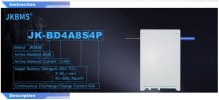
I was unable to find smart BMS for 4S LTO, so I took a chance and bought the one on the parts list, this one.
https://www.aliexpress.us/item/3256..._main.179.68be1802BfLCY6&gatewayAdapt=glo2usa

It is rated for 6S-8S LTO (see image), scroll down the link page for specs and click "View More".
Luckily, it worked for the 4S LTO configuration, as I said earlier, I limited low end voltage to 7.4-7.6V, and I have no doubt it will work for the 5S and definitely for 6S configuration.
 

Attachments

  • Capture.JPG
    Capture.JPG
    72.5 KB · Views: 3
Curious. I've spent hour after hour looking and found multiple links for that same JK BD4A8S4P BMS. Most of the specs indicate 7-8S for LTO. I only found a single link where the specs sheet indicated 6-8S, so your link makes two. I wonder if it is an issue of older/newer version of the same model? Or is it a typo in the spec sheet? There are many other spelling mistakes present in the specs/description. Anyhow, thanks for the link!

By the way, I did some measurements of my Viofo regulator that I clipped from the cable with my own bench top power supply and a 15R load on the 5v output side (I just wanted it not to be unloaded):
-The Viofo regulator does not turn on until the input voltage was above about 8.0v. At this point, the regulator provides 5.21v output. 9.0v is the minimum output of a 7S string of LTO cells.
-Ramping the PSU up to its maximum output of 19.7v, the viofo regulator maintained a steady 5.21 to 5.22v output. 19.7v closely approximates the maximum output of a 7S string of LTO cells.
-Backing the PSU down again, the regulator maintained a 5.19v output until the input voltage dropped below 5.5v

At this point, I'm guessing the "low voltage cutoff" battery saver switch (on my unit at least) doesn't really do much... But it does show that I can just reuse the original regulator without any worry.

I did not put a full 7w load on the output, nor did I monitor for any temp changes. That's next.
 
Last edited:
I did a little stress testing with the Viofo voltage regulator/converter that comes as part of the HK-4 cable kit. As I expected, it performed very well under a variety of input voltages. I connected the red & yellow wires together on the input side to my bench top PSU and loaded it with a high-capacity 4R (3R76 actual) resistor resulting in a 7.35w power draw to simulate (albeit, a bit high) being connected to a 2-ch camera (my A139 2-ch draws about 6w). Here are the results:

0v to about 7.9v input: regulator remains dormant, 0v output
at about 8.0v, regulator turns on and provides 5.25v output
9.0v in (6S LTO minimum): 5.25v out
10v in: 5.25v out
10.5v in (7S LTO minimum): 5.25v out
11v in: 5.25 out
12v in: 5.25 out
13v in: 5.25 out
13.8v in (6S LTO nominal): 5.26v out
14v in: 5.26 out
15v in: 5.26v out (regulator starting to warm up)
16.0v in (7S LTO nominal): 5.26v out
16.8v in (6S LTO maximum): 5.26v out

19.0v in: 5.30v out, thermal rise of only 13c above ambient after 30 mins of 18v input -pretty nice!
19.7v in (7LTO maximum): 5.30v out (no change in temp from 19.0v input)

Temperature readings were made on the regulator plastic case, I did not remove it from it's housing during this test. I wanted to test it "as designed." As with my first test (that used lower current draw), the regulator requires about 8.0v on the input side before the output turns on. Once turned on, the regulator maintains very consistent voltage output as long as the input stays above about 5.5v. As the input voltage dips below about 6.0v, output voltage starts to decline, maintaining about 5.0v until the regulator shuts off at about 5.5v on the input side. It seems to require about 0.3v to 0.4v of input headroom at this low input voltage level.

So, the overall conclusion is that the Viofo regulator is very robust and is compatible with both 6S and 7S LTO battery configurations. There is no need for any other regulator if you're running a 5v setup for your dashcam.
 
Last edited:
Interesting, how about the low-voltage cut-off at 11.8V, didn't it work? I am assuming you are testing regular HK4 cable and not the one that Viofo recently released for spesial order with no low-voltage cut-off?
That is why I limited voltages for 7S configuration between 11.8-18.1V.
Higher end is limited becaus above 18.1V the HK4 treats the system as 24V system and also would "protect" battery cutting off power between 18.1V and whatevere the low-voltage cut-off setting for the 24V battery.
 
I didn't see any voltage cut off at all. The regulator kept pushing out voltage all of the way down to a 5.5v input. It also never turned off as voltage climbed well above 12v. My bench PSU can only output 19.7v so I didn't test any higher voltages. It didn't turn off for over- or under-voltage at all. Go figure... I'm wondering if this behavior is because I tied red and yellow input wires together and drove them with the exact same voltage. This makes me think that maybe the voltage cutoff operate according to the differential between the red and yellow input wires rather than as a result of an absolute voltage level, but this is just a guess.

Oops, I just checked the regulator, I'm using the HK3-C regulator, not the HK4, so maybe that's part of the difference that I'm seeing, too. I don't know...

All of the above voltage readings were performed with the voltage switch in the lowest position (11.8v). As I was playing with the lower voltages (6-10v), I tried moving the selector switch to each of the other positions. It made no difference to the output voltage and the regulator never turned off until the input voltage fell below 5.5v.
 
My bad, I missed the part that you connected red and yellow wires.
All Viofo HK-# voltage converters/regulators work the same way.
When both red and yelow are powered (required to start the DVR) the regulator is in a normal recording mode, so the low-voltage cut-off is disabled.
Low-voltage cut-off is only active in parking mode, that is when power is removed from the yellow wire/ACC signal.
 
Back
Top