LTO (Lithium Titanate Oxide) – The Ultimate Battery for Dash-Cam parking mode (DIY)

.....
I think I’ll start connecting the parts for my second battery and compare to the first one. Guess there is an advantage to having to build a second battery beyond just having it cost twice as much.
Make sure to first adjust voltage potentiometer CV with the battery disconnected, and only then adjust amperage potentiometer CC with the battery connected and charging (preliminary turn CC counterclockwise to minimize initial current).
Never adjust CV with battery connected.
Hopefully no orange light.
 
Last edited:
I completed the full charge(8A)/discharge(4A)/charge(8A) cycle on reconfigured 5S battery. All good.

The only issue is that somehow I miscalculated the Relay height and now to fit it inside the same box I will need to shave the box (aluminum rib inside) or alternatively, I am thinking to switch to modular design, when the Battery eccepts only ACC power like @EricSan and Relay+Ffuse will go into separate, much smaller box as an option, in case I want to switch to battery power and higher charge rate.
The modular design is actually makes a lot of sense, I will discuss it later when done.
 
Oh no, sorry to hear that your box is a bit small, though at least you have an option for how to proceed.

Solved my orange LED issue! I had my charging voltage set too high. There isn't any documentation about what the ideal charging voltage is relative to the final voltage for any given battery configuration. Since my batteries total 16v when charged, I set the charger to 17v, figuring the charger needed some headroom. Now that I've been watching things charge, I see that when you set the charger voltage a little lower, the charger actually starts to "ramp down" the charge rate by backing off of the current when the battery approaches its limit. And all without the orange LED lighting up.

So I have voltage set just below 16v for now and everything seems to be functioning well. The battery is fully charged, the charge current ramps down as the battery approaches 16v and the LED stays off.

I guess the operative question is this: what is the actual/official charge setting relative to battery final voltage? Should they be equal? Should the charger be just a few tenths of a volt lower? Higher? I haven't been able to find any good guidance online anywhere. All of the searches I performed returned results about charging car batteries...
 
Finally! I'm glad you solved the orange light issue, I couldn't sleep well, thinking all the time what could have caused it to light up :)

The normal practice is to charge the battery pack based on the cell's max rated voltage.
I believe Toshiba specifies the max cell voltage as 2.7V, hens for 6 cells in series, the charge rate should be 6x2.7V or about 16.2V.
For the 5S, I have set it to about 13.5V.
In reality the battery pack will never reach that max voltage, because one of the cells will reach its cell limit before rest of the cells (due to some dis-balance) and the cell protection set at 2.7V will stop the charging, so the max battery pack voltage would be slightly less then 16.2V when fully charged.

As you mentioned, as charging voltage for the battery pack approaches to that max level, charger "senses" it, and starts to slowly throttle down charging current (all chargers do), which is good for the health of the battery.
 
Last edited:
Yeah, really! Given the simplicity of this battery (only 4 parts) I was struggling to figure out what I had done wrong. It's always interesting when the problem turns out to be (yet another) case of "user error."

My first battery pack is mostly complete inside of its box, so it's a little tight to work on things. I decided to piece together my second battery without a case so I could play around more easily. I set it up just like the first one and when I got the same result (orange LED), I figured it was a setting and not a bad piece of equipment or a wiring error. Since changing the current output didn't seem to impact the LED, I fiddled with the voltage output until the light went out, then measured the voltage setting again. When I saw the charge current ramping down and figured I was on to something...

I'll reset the charger output limit to 16.2v (2.7 * 6). I suspect it will behave better now. I figured the charger needed some amount of voltage headroom in order to properly charge the batteries, but this seems incorrect.

Perhaps I'll play around with measuring the efficiency of the charger next. I have some power resistors that I should be able to attach to the input and output to see what the differences are. With the current set to draw 10A from the car's utility outlet (about 8.7A going to the batteries), thermal rise of the charger board is about 17c. With a 4A setting (3.9A to the batteries), the thermal rise over ambient is only 9c. If you measured near 55c in your car, the charger will reach about 72c on a hot day with a 10A charge rate. Since the charger is specified to run up to 85c, this shouldn't cause any problems...
 
Last edited:
It turns out that this whole voltage setting thing is a somewhat sensitive affair... It's easy enough to get in the right ballpark, but precision seems to vary a bit from power cycle to power cycle. Voltage output from the charger also varies just a bit with the current load that is in place (somewhat predictable). When I initially set the charger's output level to 16.0v, there was a "sharp" turn-off charging current. It went to about 16.1v while drawing 4A and then the charge current just dropped to 0A with no ramping down. So, I changed it to15.90v and it behaved better with a ramp down of the current before it stopped charging. This is the behavior that I was looking for.

I have a heavy duty resistor bank that I use for output testing of DIY class-A amplifiers that works well for testing the charging board, it can easily absorb over 300w of power. It also has a light switch in the middle that I can use to change the resistive load from 8R to 4R. For the battery charger board, this works out to either a 2A load or a 4A load.

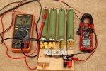
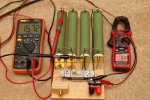
With a 2A load, I adjusted the charger board to output 15.9v. When I flipped the switch to provide a 4A load, the voltage output dropped to about 15.7v. But as I switch back and forth from a 4R load to an 8R load, the output voltage moves around a little. See the images below. It's a bit of a trial and error process to set the voltage so the current ramps down as the batteries get charged up. My orange meters are somewhat inexpensive, but they track accurately on all DC and AC scales to a calibrated lab style Agilent bench meter with six digit accuracy.

Here is an 8R load (switch to the right) that pulls about 2A from the charger board at 15.89v
IMG_10177.JPG

Here is a 4R load (switch to the left) that pulls about 4A from the charger board at 15.72v
IMG_10178.JPG
 
Last edited:
Did some measurements on power efficiency tonight. The voltage that we’re using the charger at (12-16v) is well below the voltages in the published efficiency table (which shows 96-98%). I have a few 50w 0.15ohm power resistors that I measured with a calibrated low-ohm meter and recorded their actual resistances. I put one before the charger board and one after it then turned on the charger and measured voltage drop across each resistor. I made each measurement (resistor value and volt drop) multiple times and averaged my readings before moving forward with any calculations.

At a ~2A charge rate, I measured 35.4w into the charger board (0.375 volt drop across 0.136 ohm resistor with 12.89v reaching the charger) and 31.8w out of the charger (0.295 volt drop across 0.149 ohm resistor at 16.07v out of the charger). This is an efficiency of 90%

I had to drain the battery a bit to get the charger/BMS to charge at a higher rate. With a ~4A charge rate, I measured 73.3w into the charger board (0.8116 volt drop across 0.136 ohm resistor with 12.27v reaching the charger) and 65.7w out of the charger (0.6178 volt drop across 0.149 ohm resistor at 15.8v out of the charger). This is an efficiency of 90%.

This is a bit below the published 97-98% efficiency, but these figures are posted only for 24 to 48 volt conversion, 48 to 48 volt conversion (which I don't quite get), and 48 to 24 volt conversions. Still, the performance is good for this purpose and overall heat generation is pretty reasonable.

Edited to provide more data for my calculations.
Very interesting, 90% is kind of low for this charger.
I think equipment resolution for such a small numbers may play some role here, a little change to a very small numbers could result in noticeable difference.

My first charger which is in LFP battery now, was showing about 96-97% efficiency and was running really cool, but I don't remember at what voltage was the battery, probably somewhere in the mid-range, and the orange light was definitely Off, charge amperage was about 7.3A.

The two other chargers (I got from different seller) are showing about 91-92% when the Battery is completely empty and ...... the orange light is ON, yes that orange light, which I didn't see in my first charge cycle somehow, I guess I missed it or didn't pay attention at the beginning of charge?? :mad:
However, as the battery gets in to mid-range nominal voltage, the orange light would turn Off and the efficiency is increasing to up to 95% with average efficiency at about 93-94%, charge rate is about 8A.

Anyway, I am re-running the charging cycle and recording series of videos for entire charging process, starting with completely discharged Battery set to about 9.3V and with inline INPUT and OUTPUT power meters to see initial, final and average efficiency, and also to verify that the orange light which is initially On will turn Off after battery voltage reaches about 0.9 of the set to 13.5V charge voltage or at 12.2V.

I will post videos soon.
 
I don't have any software to edit and stitch the video files, so here are 4 original videos for my re-configured 5S LTO battery charging process with smaller more efficient charger.
The battery's voltage range is set at 13.5V max and 9.25V min, charging current is set at 8A, providing 100W average charge rate.


Last edited:
For comparison,
Here are 2 videos of my initial charging process of a 4S LFP battery with the similar charger (the first one, from a different seller).
LFP Battery voltage range is set to 14.4V max and 10.8V min, charging current is set to 7A, giving an average charging rate of about 90-100W.
Starting at about 10.9V, it only took about 10-12 minutes to reach 13V (0.9 from 14.4V) or about 10% SoC for the orange light to go out, I didn't expect it to go out that fast and actually missed the exact moment. The charger temperature was only about 34°C, indicating high efficiency.

This first charger used for LFP Battery seems to be more efficient than the other two I bought from another seller that I use for LTO, even though they look exactly the same.
Or maybe the efficiency difference is due to the type of battery, LTO vs LFP?
I am tempted to swap the chargers to check.


I couldn't resist and charged completely flat LFP battery with the charger I tested with the LTO, to see if different Battery type will make any difference… and to some extent it does.

The charger was adjusted to 14.4V and 7A as the original one.
I used the same test setup as for the battery with inline In/Out power meters.
Starting at about 10.9V, it only took about 5-6 minutes to reach 12.9V (0.9 from 14.4V) for the orange light to go out.
However, from the very beginning the efficiency was 95.3% and it stayed there.
The charger temperature was about 46°C, which is more than the original charger at about 37°C.

I then re-tested the LFP battery with the original charger to verify the time it takes for the orange light to go out – it was 5-6 min. and not 10-12 min as I assumed when I missed it during the first test.

Conclusions:
When charging from empty, the LFP battery voltage increases much faster to midrange level than the LTO.
For the LFP at the beginning of the charge, even with orange light on the efficiency does not suffer and is about 95% throughout the charge.
For the LTO, initial efficiency is about 92% and as voltage reaches midrange level efficiency is increases to about 95%, with average of about 93-94%.
Due to temperature difference, the original LFP charger is likely 1-2% more efficient, I guess I got lucky with that one.
 
I suspected there would be a difference in efficiency/time/heat/etc between charging different battery chemistries, thanks for the confirmation. Looking at your power meters, I'm wondering if I calculated efficiencies incorrectly... I also did not pay attention to state of charge while I made my measurements, so this might be a factor as well.

When you make temp readings, the critical element is to reference temp rise over the ambient temperature, rather than just what the temp is. This provides a reference that should be constant from environment to environment. Thus, a temp rise of 10c over ambient will (usually) be the same, regardless of the ambient temperature. When I build Class-A amplifiers (simple circuit, fewer parts, low efficiency, high heat generation), the design goal is always to keep thermal rise to 25c over ambient. Building/testing in summer vs winter makes a big difference in final temp, but it's always 25c over ambient.

Thanks for posing the additional videos! Great stuff.

Put my first battery in my son's car today to start some real-world testing of charge rates and overall performance. I just spent the better part of a week polishing it (wash, clay, chemical decontamination, then a 3-stage paint correction) and finally applying a two-layer ceramic coating to keep bird droppings and tree sap from etching into the clear coat again. Looks pretty nice now without all of the scratches, scuffs, and swirls in the paint.
IMG_00758.JPG
 
Finally! I'm glad you solved the orange light issue, I couldn't sleep well, thinking all the time what could have caused it to light up :)


In reality the battery pack will never reach that max voltage, because one of the cells will reach its cell limit before rest of the cells (due to some dis-balance) and the cell protection set at 2.7V will stop the charging, so the max battery pack voltage would be slightly less then 16.2V when fully charged.

Perhaps you should look at balance charging the packs, of course you would need to wire the batteries differently. Most of the Li* used in the RC hobby are balanced charged and that provieds an equal level of charge to each cell. Providing the cells are similar in their Internal Resistance (IR) and chemistry. Do a search on LiPo balance charging and you will find plenty of diagrams. You would also need to get a 'smart' charger that can be set for your cells chemistry type, voltage and capacity.
 
Perhaps you should look at balance charging the packs, of course you would need to wire the batteries differently. Most of the Li* used in the RC hobby are balanced charged and that provieds an equal level of charge to each cell. Providing the cells are similar in their Internal Resistance (IR) and chemistry. Do a search on LiPo balance charging and you will find plenty of diagrams. You would also need to get a 'smart' charger that can be set for your cells chemistry type, voltage and capacity.
We are balance charging.
- Battery pack cells are the same chemistry, and internal resistances are close but not necessarily the same for all of the cells.
- Battery packs are equipped with smart BMS (Battery Managment System) with all the required protections.
- BMS has the integrated balancing board/function, to maintain cell voltages equal within the minimum allowed divination.
- Charger is adjustable with constant voltage and constant current, CV-CC.
- Charging voltage (CV) is set according to battery chemistry and number of cells in series, charging current (CC) is set as needed, but not to exceed max allowed according to battery Ah rating.

In ideal world, the fully charged voltage for all of the cells could be the same, resulting in maximum voltage for the pack, however in a real world there is always some minimal dis-balance and as soon as one cell reaches the limit, BMS will stop the charging.
 
In ideal world, the fully charged voltage for all of the cells could be the same, resulting in maximum voltage for the pack, however in a real world there is always some minimal dis-balance and as soon as one cell reaches the limit, BMS will stop the charging.

I missed where the BMS was doing a 'true' balance charge. Balance charging, as I know it, is where each battery is charged to its max potential based on a charging algorithm that takes into account the chemistry, capacity, IR and voltage of the battery cell. In the RC world, balance charging on a pack continues until all cells are charged to a max calculated capacity based on the state of 'goodness' of each cell. Thus, you could have a 4 cell battery pack with all 4 cells at different capacity, but, each cell is at its max capacity based on cell quality. Balance charging of a pack, as I know it does not end when any given cell in that pack reaches the max capacity/potential of that cell. I attempted a look at your wiring but I can't see it well enough to know what is wired to what and how.

There are true LTO charges in the hobby world, one is made by Junsi. I think some of the smaller Junsi iChargers in Nouth America do not offer LTO, but I believe they do in Asia. Google Junsi or hilltop dot com ( i think ) and look at the Junsi chargers. A bit expensive, but they do true balance charging if the cells properly wired, and you have a balance harness.
 
Those RC chargers look interesting, but also seem to be a poor fit to this specific application. I also think we're exploring differences between charging approaches that might be less important than they appear. It seems like the primary difference is 1) delivering charge current to "each cell" in the battery pack vs 2) delivering charge current to the "battery pack" and actively balancing the voltage of each cell along the way. There is a difference, but it seems to be a small one, as cells are individually managed in each case. The Junsi chargers don't seem to be a good fit with this application: they are encapsulated (hard to build into something else), large, and judging by the size of the heatsinks I see in some images (including a built in fan attached to the sinks), they don't appear to be terribly efficient, meaning they generate a significant amount of heat. This would make them a poor fit for a hot environment inside of a closed car.
 
So here is the final implementation of my LTO battery box. I made two of these, the one for my son was painted black and the one for my car stayed blue.

Here it is all connected together on the floor. This is just a wiring proof of concept to make sure that everything works as intended:
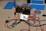
IMG_10175.JPG

The battery pack is held into the case with some plumber's strap that is screwed to the bottom panel of the chassis. I also had to move the chassis feet out of the way (closer to the edge) because the screw head interfered with where the batteries would sit.
IMG_10179.JPG

The bottom of the battery pack received some double stick thermal transfer tape to help hold it in place as well:
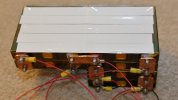
IMG_10180.JPG

Here it is with the battery strapped in place:
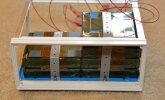
IMG_10181.JPG

The BMS and charger are attached to what I refer to as the "front" panel. The BMS is held in place only with tape, while the charger is screwed to the panel and I put some thermal paste between the charger and chassis panel. Power entry and camera power connectors are on the opposite panel:
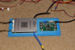
IMG_10152.JPG

Here it is, almost ready to close up. The charger and BMS are covered with tape and I placed a left over rectangle of plastic between the battery terminals and the BMS to prevent shorting should the battery or BMS/Charger come loose in the chassis.
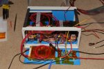
IMG_10153.JPG

The battery pack for my son's car sits on the rear passenger floor (black carpet), so it got a coat of black truck bed liner to blend in better. The BMS power button wire had to be extended to reach where I needed it to. This lets me remove the cover without worrying about the wires:
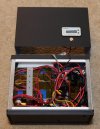
IMG_10182.JPG

And here it is, all buttoned up and ready for action:
IMG_10275.JPG

Set to 5.0A charge rate is just about perfect for leaving the BMS on 24/7. When he gets home from work, the battery pack voltage is within a few thousandths of where it was the night before. It seems that the BMS consumes about 1.4w, so I don't have any problem with leaving it on all of the time.

Big thanks to GPak for documenting his work and inspiring my obvious copy-cat implementation. I don't expect any temp-related problems with this battery pack and the batteries themselves should last about 20 years or so. I suspect the batteries might just outlast the car and the rest of the electronics... Should any problems arise with the electronics, I can fix this one myself :)
 
Last edited:
So here is the final implementation of my LTO battery box. ... ...... ....... ..... Should any problems arise with the electronics, I can fix this one myself :)
Very nice!!
And the last sentence - "Should any problems arise with the electronics, I can fix this one myself" - is priceless!!(y)
 
I missed where the BMS was doing a 'true' balance charge. Balance charging, as I know it, is where each battery is charged to its max potential based on a charging algorithm that takes into account the chemistry, capacity, IR and voltage of the battery cell. In the RC world, balance charging on a pack continues until all cells are charged to a max calculated capacity based on the state of 'goodness' of each cell. Thus, you could have a 4 cell battery pack with all 4 cells at different capacity, but, each cell is at its max capacity based on cell quality. Balance charging of a pack, as I know it does not end when any given cell in that pack reaches the max capacity/potential of that cell. I attempted a look at your wiring but I can't see it well enough to know what is wired to what and how.

There are true LTO charges in the hobby world, one is made by Junsi. I think some of the smaller Junsi iChargers in Nouth America do not offer LTO, but I believe they do in Asia. Google Junsi or hilltop dot com ( i think ) and look at the Junsi chargers. A bit expensive, but they do true balance charging if the cells properly wired, and you have a balance harness.
About ten years ago I used to fly RC planes for some experiments and also for fun.
I still have a couple of RC balance chargers and Li-Po batteries that I charge from time to time to maintain storage voltage.

In addition to what @EricSan already mentioned, I can add that the main difference between RC chargers and our Charger+BMS with balancing function is that the RC charger only balances the cells during charging, and then disconnected from the battery when charging is complete, whereas in our case the BMS protects and balances the battery during charging and also during discharging phase, permanently connected to battery.
You can see the BMS balancing harness on one of @EricSan pictures above. (thin red wires with yellow terminals)
 
Last edited:
And here it is in its new home! The velcro strap actually passed through the trunk liner, so it's held pretty securely in place. Have to see how the charge rate works out over the next few weeks and if it needs to be adjusted.

Edit: There is only 1 cable in (12v charge from the switched utility outlet also in the trunk) and only 1 cable out to the camera (3 conductors: 5v power, ground, and 5v parking mode trigger).

LTO Battery Installed.JPG
 
Last edited:
Back
Top