sofaspud
Member
Sorry this is a long post, but hopefully worth a read...
from this original attempt for a twin lens mounting,
https://dashcamtalk.com/forum/threads/mobius-remote-lense-s.5125/
I finally got around to having a more enclosed housing 3D printed by a commercial service.
I was thinking along the lines of a case similar to the ultrasonic sensor cases on older retrofit car alarms. To create the design, I used OpenSCAD, a free 3D design tool. This is great for making geometric shapes, but is more difficult if you want to create more free flowing shapes as you create items by using a construction (text) file rather than a graphical interface. Although it seems daunting, I found it perfect for this project as it forces you to use absolute measurements rather than moving stuff with a cursor.
http://www.openscad.org/
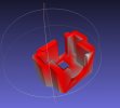
To avoid getting too involved with trig during the design work I created the individual lens housings as shown below.
I still use the narrow (lens A) units, but the case design takes both this & the wider angle versions (lens B & C) using the same principle as the Mobius case(see the piccies below)

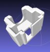
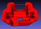
From this I then replicated & merged the shapes at the required angles & infilled the gaps to create this:

I also included some air slots to get some (limited) convection cooling for the imaging plate. Not entirely sure these are needed as the Mobius case doesn't use such a scheme, plus the lens' are no longer subjected to the heat of the other chips in the Mobius.
I also added a mounting slot to the upper half.
The lens's are mounted at 39 deg from the straight, to give an included angle of 78 deg. This allows a bit more overlap than the metal brackets I used before. I found with the angle used before, something of interest immediately ahead of the car was never quite in full view on either camera. The angle used on this design cures that issue.
The lens' are held in place by the cut out(s) in the design which also clamps down on the lugs of the lens body to hold it securely. 2 of these cut outs are included so I can use A, B, or C len's as I choose, in the same way you can with the Mobius case. I don't intend to use the wider angle on the twin case as it is angled for the narrow lens.
Because of the way the print bureau I used sells 'space' on their printer in defined volumes, I had spare volume with only the twin design included, so had some single lens holders printed as well. I plan to have a play with a single wide angle lens using the single lens cases.
When the design was complete & the printing volume packed full, I sent it of to the print bureau. A couple of days later I got back these:


After 'cleaning' & painting:

I actually roughed up the surface further with some 40 grit to try & get a texture similar to the plastic moldings used in cars so it would blend in better
The lens is held in place in the same manner as the Mobius case holds them. The ribbon connector sits behind the lens body & the extension cable exits through the slot in the back of the case.
I deliberately made the space for the ribbon connector as small as possible to reduce the size of the case. I was a bit nervous as the ribbon is bent quite severely, but having fitted them carefully it works & has given no trouble for the few days I've been using these. As the cables don't move when installed there shouldn't be any flexing on the bent ribbon so I don't expect there to be any trouble with this.
The 2 halves of the design are secured using #0 self tappers in countersunk holes in the lower half of the case. I also used registration pins in the design to ensure the 2 halves align correctly.

& a single lens case, B & C type lens's use the forward mounting slot same as the Mobius:

Assembled unit, as an indication of scale the squares in the background are 5mm:

To attach these to the screen, for now I use a simple metal bracket, the mounting tongue is sized to allow a small amount of sideways twist, up & down adjustment is through bending the bracket.

And installed in the car:

Not really visible due to the reflections on the screen, so in the garage:


The Mobius bodies are still in the same location as before, not entriely satisfied with this as one of them can be seen from outside the car as seen in the above pic.
I intend to make some different brackets to relocate them, although I'm limited by the length of the extension cables.
The lens extension cables I hid behind the plastic moulding covering the rear view mirror mounting visible in the following picture

Limitations/benefits/errors:
I already knew the principle of the idea worked from the previous project, so the only concern for this project was the severe bend on the ribbon cable. This proved not to be a problem.
The only change from the previous is there is now more overlap between each lens to better cover the front of the car, as I wanted.
I think these look much more discrete, and so are less noticable from outside.
The lens required re-focussing as I originally had them mounted on the metal brackets using the imaging set screws & so disturbed the focussing when I removed them. I did this once the lens were mounted in the case, but before installation in the car.
The bureau I used uses the sintering method which is basically fusing nylon granules layer by layer. This allowed more complex shapes as the granules support each other during the print.
When I got the prints back, there was a lot of waste to clean out. There is a lot of nylon powder that was not fused & tends to fill any cavities in the items. They do clean out the worst & I could have paid extra & have them clean (wash) them further & even 'polish' them, but chose not to.
Due to the heat involved in the sintering process, I found that if you have a large flat area in the design, then allow greater distance between this & other items in the volume, as the conducted heat semi fuses nearby items. Doesn't fully fuse them, but makes cleaning afterwards more a touch more involved. Things like very small diameter pilot holes in the design are prone to this limit & required drilling out, next time I would make greater allowance for this.
The design I sent off was for the metal bodied lens'. As we now know, the newer FRP bodies are slightly larger. Not an issue for me as the lens' I have are the metal versions, & to fit the FRP will require a little bit of 'fettling' to carve out a slightly larger area. The case walls are thick enough to do this though. If I was to do anything further with these ideas then it is simple to enlarge the cut outs in the design files to suit the FRP lens'
from this original attempt for a twin lens mounting,
https://dashcamtalk.com/forum/threads/mobius-remote-lense-s.5125/
I finally got around to having a more enclosed housing 3D printed by a commercial service.
I was thinking along the lines of a case similar to the ultrasonic sensor cases on older retrofit car alarms. To create the design, I used OpenSCAD, a free 3D design tool. This is great for making geometric shapes, but is more difficult if you want to create more free flowing shapes as you create items by using a construction (text) file rather than a graphical interface. Although it seems daunting, I found it perfect for this project as it forces you to use absolute measurements rather than moving stuff with a cursor.
http://www.openscad.org/
To avoid getting too involved with trig during the design work I created the individual lens housings as shown below.
I still use the narrow (lens A) units, but the case design takes both this & the wider angle versions (lens B & C) using the same principle as the Mobius case(see the piccies below)
From this I then replicated & merged the shapes at the required angles & infilled the gaps to create this:
I also included some air slots to get some (limited) convection cooling for the imaging plate. Not entirely sure these are needed as the Mobius case doesn't use such a scheme, plus the lens' are no longer subjected to the heat of the other chips in the Mobius.
I also added a mounting slot to the upper half.
The lens's are mounted at 39 deg from the straight, to give an included angle of 78 deg. This allows a bit more overlap than the metal brackets I used before. I found with the angle used before, something of interest immediately ahead of the car was never quite in full view on either camera. The angle used on this design cures that issue.
The lens' are held in place by the cut out(s) in the design which also clamps down on the lugs of the lens body to hold it securely. 2 of these cut outs are included so I can use A, B, or C len's as I choose, in the same way you can with the Mobius case. I don't intend to use the wider angle on the twin case as it is angled for the narrow lens.
Because of the way the print bureau I used sells 'space' on their printer in defined volumes, I had spare volume with only the twin design included, so had some single lens holders printed as well. I plan to have a play with a single wide angle lens using the single lens cases.
When the design was complete & the printing volume packed full, I sent it of to the print bureau. A couple of days later I got back these:
After 'cleaning' & painting:
I actually roughed up the surface further with some 40 grit to try & get a texture similar to the plastic moldings used in cars so it would blend in better
The lens is held in place in the same manner as the Mobius case holds them. The ribbon connector sits behind the lens body & the extension cable exits through the slot in the back of the case.
I deliberately made the space for the ribbon connector as small as possible to reduce the size of the case. I was a bit nervous as the ribbon is bent quite severely, but having fitted them carefully it works & has given no trouble for the few days I've been using these. As the cables don't move when installed there shouldn't be any flexing on the bent ribbon so I don't expect there to be any trouble with this.
The 2 halves of the design are secured using #0 self tappers in countersunk holes in the lower half of the case. I also used registration pins in the design to ensure the 2 halves align correctly.
& a single lens case, B & C type lens's use the forward mounting slot same as the Mobius:
Assembled unit, as an indication of scale the squares in the background are 5mm:
To attach these to the screen, for now I use a simple metal bracket, the mounting tongue is sized to allow a small amount of sideways twist, up & down adjustment is through bending the bracket.
And installed in the car:
Not really visible due to the reflections on the screen, so in the garage:
The Mobius bodies are still in the same location as before, not entriely satisfied with this as one of them can be seen from outside the car as seen in the above pic.
I intend to make some different brackets to relocate them, although I'm limited by the length of the extension cables.
The lens extension cables I hid behind the plastic moulding covering the rear view mirror mounting visible in the following picture
Limitations/benefits/errors:
I already knew the principle of the idea worked from the previous project, so the only concern for this project was the severe bend on the ribbon cable. This proved not to be a problem.
The only change from the previous is there is now more overlap between each lens to better cover the front of the car, as I wanted.
I think these look much more discrete, and so are less noticable from outside.
The lens required re-focussing as I originally had them mounted on the metal brackets using the imaging set screws & so disturbed the focussing when I removed them. I did this once the lens were mounted in the case, but before installation in the car.
The bureau I used uses the sintering method which is basically fusing nylon granules layer by layer. This allowed more complex shapes as the granules support each other during the print.
When I got the prints back, there was a lot of waste to clean out. There is a lot of nylon powder that was not fused & tends to fill any cavities in the items. They do clean out the worst & I could have paid extra & have them clean (wash) them further & even 'polish' them, but chose not to.
Due to the heat involved in the sintering process, I found that if you have a large flat area in the design, then allow greater distance between this & other items in the volume, as the conducted heat semi fuses nearby items. Doesn't fully fuse them, but makes cleaning afterwards more a touch more involved. Things like very small diameter pilot holes in the design are prone to this limit & required drilling out, next time I would make greater allowance for this.
The design I sent off was for the metal bodied lens'. As we now know, the newer FRP bodies are slightly larger. Not an issue for me as the lens' I have are the metal versions, & to fit the FRP will require a little bit of 'fettling' to carve out a slightly larger area. The case walls are thick enough to do this though. If I was to do anything further with these ideas then it is simple to enlarge the cut outs in the design files to suit the FRP lens'
Last edited by a moderator:
")