Output power connector for Viofo BP100

Dashcam1955

New Member
Joined
Jun 1, 2026
Messages
2
Reaction score
2
Location
Boise
Country
United States
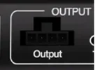
Hello, I am looking for the exact name/part number for the NON-USB power output connector for the Viofo BP100. Viofo wouldn't be more specific than calling it a "4-pin panel mount wafer connector (with keyed notch)". In my experence this looks more like a 'euroblock connector 4-pin' but no dice with a google search. I attached a photo of the part number that I need. Viofo customer tech support was no help. I need the female (opposite) connector that is included with the Viofo wiring kit. Thanks in advance.
 

Attachments

  • img_o18pb3fo84_88459bfdcfbae9351982b36d10da1d0aa20b729fffb2e4aa4bce4830554563ac.webp
    img_o18pb3fo84_88459bfdcfbae9351982b36d10da1d0aa20b729fffb2e4aa4bce4830554563ac.webp
    7.2 KB · Views: 9
The female 4-pin plastic Molex connector and female terminal pins used to connect with the BP100 12V output power connector are the same items used with a variety of EGEN produced dash camera battery packs. I created a video a few years ago showing the part numbers and how I crimp the terminal pins onto the cable wires.

I use the 20 AWG to 24 AWG terminal pins when I'm connecting a dash camera hardwire cable/kit directly to the battery pack since the dash camera power cables "never" have a wire gauge larger than 20 AWG. I use the 18 AWG terminal pins and a 3-wire cable with 18 AWG copper wire if I'm running the power cable from the dash camera battery pack to a remote location in the vehicle. I've created several power cables using both Molex connector types. I had not used the 18 AWG terminal pins/connectors when I created my video, but I have several times over the past year or two.

The main thing about which wire goes into which Molex connector terminal pin position is based on the power type [constant, switched, or ground]. VIOFO dash camera hardwire kit cables have a red wire for the constant power wire and a yellow wire for the switched/accessory power, and a black wire for ground. Other dash camera companies will use swap the red and yellow wire colors. Make sure you identify the type of power required by the dash camera power cable to make sure the correct Molex connector terminal pin position is used.

The VIOFO hardwire kit wire insulation tends to be thicker than most other wires used for this purpose. It can be a bit more challenging to crimp those wires with thicker insulation into the Molex terminal pin since the thick wire insulation doesn't "fit" well into the end part of the terminal pin that is intended to be crimped onto the wire insulation. I've found that if I strip just a little more of the wire insulation off the wire and crimp the bare wire in that final [wire insulation] crimp area, it works much better with the VIOFO hardwire kit wires. Just make sure not to strip off too much which can result in the bare wires being exposed beyond the plastic Molex connector.
 
If I was to send you $100, or made a $100 donation to your favorite charity, would you build me a 6 inch cable that would go between my BP100 and the cable that in circled in the photo below? I know just enough about electronics to get me to this web fourm. From what I understand the yellow being energized takes the S329 out of parking mode. I imagine that all a person would have to do is use the red that comes out of the BP100 port on the jack and tie it in to the yellow on the 6 inch cable that I described, connecting the jumper to the connector that is right now in the BP100. Having the 6 inch jumper cable makes it so that I can switch between setups.

It would be really cool to have the above setup on an in-line switch. Ideally such a switch would be setup so it is illuminated in what is normal driving mode and when switched into the alt-mode the light would be not illuminated as this would further drain the BP100 while parked.

I don't feel comfortable messing with the current dash setup as it was installed by a car stero company because I have vents running though the ceiling for HVAC. Having said that, the cords in the professional install were just long enough to reach the S329.
 

Attachments

  • img_c7dhd2p63a_71875cd56873e9998b62b7bd55388033575e43f25f33d74413a3e39e633cda47.webp
    img_c7dhd2p63a_71875cd56873e9998b62b7bd55388033575e43f25f33d74413a3e39e633cda47.webp
    60.3 KB · Views: 7
If I was to send you $100, or made a $100 donation to your favorite charity, would you build me a 6 inch cable that would go between my BP100 and the cable that in circled in the photo below? I know just enough about electronics to get me to this web fourm. From what I understand the yellow being energized takes the S329 out of parking mode. I imagine that all a person would have to do is use the red that comes out of the BP100 port on the jack and tie it in to the yellow on the 6 inch cable that I described, connecting the jumper to the connector that is right now in the BP100. Having the 6 inch jumper cable makes it so that I can switch between setups.
The 3-wire cable that plugs into the BP100 12V 4-pin Molex connector output port already has the [yellow - VIOFO wire color] accessory/switched power wire present. The BP100 will manage the power on that wires so the dash camera's hardwire kit knows when to turn off the accessory/switched power to the dash camera.

I'm not quite understanding what adding the switch will do for you since that will sidestep the automated accessory/switched power management by the BP100.
 
From the photo and Viofo’s description, it doesn’t look like a typical Euroblock connector to me. My first guess would be some type of JST-style 4-pin connector, but it's hard to be certain without knowing the pin spacing. If you can measure the pitch between the pins or post a close-up of both sides, that would make it much easier to identify. Hopefully someone with a BP100 wiring kit can check and confirm the exact part number.
 
Back
Top