Uninterruptible power supply using 5V power bank

Just as the circuit is drawn. One output wire splits into two, one for each cam. You can use the jump-pack's ciggie outlet and a "Y" splitter or hub to do this. These are simple splitters; there's no need for boost circuits here.

No problem for the car feeding the whole thing while the car is running as it's only a few amps total being drawn. All car alternators have far more reserve power than this.

Phil
 
can anyone explain how does the system from OP works by having the relays always charged? i mean, the positive bus can be powered by the main power or the power bank, so the coil in the relays/optocoupler will be always charged and the circuit path should always be on... i guess the trick is done with the short between the NO1 and NC2, but can't seem to understand how :(.

i am building my solution based on a DPDT automotive 12V relay but would like to understand how this magic happens so to maybe improve the circuit and spare some redundant connections
 
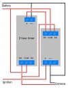
My solution which suits my application is to use a 2 hour timer and a single pole relay configured as per my diagram. Ignition circuit powers the camera while engine is running but when ignition is switched off, the 2 hour timer initialises to continue powering the camera from the cars battery.
This may not be suitable for a lot of people but it's adequate for short term parking at the shops.

Relays.JPG
 
IMG_1884.JPG
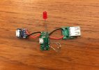
This is what I put together.... you can use all your own power banks and cables as this device only handles the switching of the power from when the car is on to the power bank when the car is turned off. If I want parking mode to work then I just hook up the appropriate D signal wire. I am going to get a small project box to stuff this in. Dimensions are about 1x1 inch
 
View attachment 48774
This is what I put together.... you can use all your own power banks and cables as this device only handles the switching of the power from when the car is on to the power bank when the car is turned off. If I want parking mode to work then I just hook up the appropriate D signal wire. I am going to get a small project box to stuff this in. Dimensions are about 1x1 inch

Can you describe the hardware used?
 
Guys, it's just TPS2113A breakout board with two USB connectors on PCB, no magic here... Just smaller clickless "switch" as the OP's (and without interrupt).

tps2113a-power-multiplexer-carrier-6.png
 
That's some ad you posted...

...but why here?
 
That's some ad you posted...

...but why here?
Because he's(?) a big time spammer. 100 posts in the last few hours and they're all essentially the same. Reported to @DashCamMan and they, and the poster, should be gone in fairly short order.
 
This is what I put together.... you can use all your own power banks and cables as this device only handles the switching of the power from when the car is on to the power bank when the car is turned off. If I want parking mode to work then I just hook up the appropriate D signal wire. I am going to get a small project box to stuff this in. Dimensions are about 1x1 inch
Guys, it's just TPS2113A breakout board with two USB connectors on PCB, no magic here... Just smaller clickless "switch" as the OP's (and without interrupt).

tps2113a-power-multiplexer-carrier-6.png
It seemed interesting to me - switching power between PowerBank and the car’s power source without a break.
I did not find it on Amazon and AliExpress, it seems that this module is only here: Pololu https://www.pololu.com/product/2596
But the cost of delivery ... :eek:
I still found a supplier in Russia and ordered myself this module. It will be interesting to install and check.
 
Last edited:
Back
Top