I understand current & voltage well, I just forgot i had put the multimeter in series with the power supply as I had already soldered in the USB socket.
The problem was your statement "the amperage I measured above is total for the camera plus the inefficient regulator so the camera will probably take less than half that".
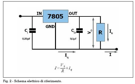
I guess you're measuring the current between vehicle 12V and 7805 pin 1, call it 502mA. This is I in the diagram. That current will be split between the regulator operating current (to ground through pin 2, shown as Iq) and the load itself (to ground through pin 3 then the camera (R), and is shown as Io).
The regulator draws very little current to do its job - if you measure the current between 7805 pin 2 and ground, it'll be about 2mA depending on the 7805 chip itself. This is Iq in the diagram above.
The remainder (500mA) goes out of pin 3 and through the camera, Io in the diagram. The voltage at pin 3 is 5V, so the internals of the 7805 need to "absorb" the other 7V whilst passing 500mA.
The point is that the camera draws pretty much all of the measured current. The 7805's inefficiency isn't from its regulation control circuitry, it's from the way it "gets rid of" the excess voltage.
I would have built a switching regulator, except I found (as you have) that I can't get close to the price of a pre-assembled one. I really can't fault
mine: small, well-packaged, runs cold, capable (5V 3A from alleged input of 8-23V) and cheaper than I could get the IC on its own.