Amateur here. Could someone confirm both the ACC and BATT need wires to get camera to power up?

AustenKorowski

New Member
Joined
Oct 2, 2021
Messages
8
Reaction score
0
Location
South Bend, IN
Country
United States
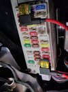
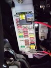
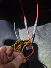
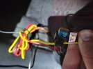
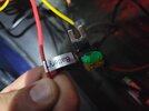
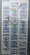
I'm using fuse taps with the Viofo kit but accidently only have one fuse tap of the correct type.

Long story short I corrected the ground and wired the ACC (red) and it's not powering on. I thought I was doing something wrong until I came across a thread that makes it sound like it's a common misconception. That ACC, BATT, and Ground all need connected for it to work at all?

Thanks
 
@austenkoroswski
Nice photos.
You are right all wires need to be connected.
The black wire to the car metal frame.
The red wire to the battery eg always on power.
The yellow wire connected to something that is only on when the ignition is in accessories or even in ignition mode.
 
There have been posts that if you're concerned about battery drain, you can connect the red and yellow to the same ignition source.

Maybe someone can confirm.

Or, if you don't want parking mode, the 2 wire Nextbase kit works perfectly with the V3
 
There have been posts that if you're concerned about battery drain, you can connect the red and yellow to the same ignition source.

Maybe someone can confirm.

Or, if you don't want parking mode, the 2 wire Nextbase kit works perfectly with the V3
I think Viofo mentioned a problem with doing that in a recent post.

It won't recognise the voltage drop when reconnected or something like that.
 
All three wires need to be connected.

You can connect the red and yellow together, but this will bypass the low voltage cutoff feature and parking mode won't work. Not an issue if connected to an ACC fuse and you don't need parking mode.
 
How do we know in which direction the current flows through the fuses in the block from the photo?
For example, in my car, one row of fuses has voltage on the top leg, and another on the bottom.
And my fuse taps "+" and "ACC" are pointing in different directions.
 
How do we know in which direction the current flows through the fuses in the block from the photo?
For example, in my car, one row of fuses has voltage on the top leg, and another on the bottom.
And my fuse taps "+" and "ACC" are pointing in different directions.
images

If there is a gap in line with the fuses that are usually active and if your vehicle does not have that equipment, there will be no socket on one side. On the full side there is energy. When you remove the fuse, you can enter which side has energy with the help of a multimeter.
 
images

If there is a gap in line with the fuses that are usually active and if your vehicle does not have that equipment, there will be no socket on one side. On the full side there is energy. When you remove the fuse, you can enter which side has energy with the help of a multimeter.
I know all this.
I’m interested in how you determined from the photo in the first post how fuse taps should be installed... :unsure:
 
I know all this.
I’m interested in how you determined from the photo in the first post how fuse taps should be installed... :unsure:
Do you have a picture of your car's fuse diyagram? Or what is the make and model of your vehicle? I can describe. If you have a multimeter or a 12 volt light bulb.. contact the negative pole to the ground and the positive pole to both sides of the gap in the panel. if the bulb lights up or the multumometer shows 12v, that side is the 12 volt part.
 
Do you have a picture of your car's fuse diyagram? Or what is the make and model of your vehicle? I can describe. If you have a multimeter or a 12 volt light bulb.. contact the negative pole to the ground and the positive pole to both sides of the gap in the panel. if the bulb lights up or the multumometer shows 12v, that side is the 12 volt part.
I have only one question:
How did you determine from the photo in the first post that the fuse tap was installed incorrectly?
 
I have only one question:
How did you determine from the photo in the first post that the fuse tap was installed incorrectly?
You could ask this directly. The picture shows the connecting metals of one side. On the other hand, there are also uninsured parts. I wrote what I thought was the opposite. I wrote this because I think it needs to be checked and it's important that it works in fuse tap use. If the vehicle brand and model had been specified, I could have spoken clearly about its direction. If I come to you, the fuse type scheme and structure of each car is different. Therefore, I cannot directly say that the direction is as follows. I say I think so, which means it needs to be checked. In my vehicle, some parts face the opposite side, other parts face the opposite side. I wanted to write because there are many people who do not know and overlook this. is it enough?
 
Alright guys. Looks like I need to purchase a voltmeter or test bulb. I have good connections on 2 new taps. This time both the BATT and ACC plugged in and still no power.

I've tried multiple fuse locations and tried flipping the taps (but keeping them the same as each other). The guy above mentioned his are facing opposite directions from each other. Could that actually be a solution to try in the meantime?

I'll find more patience to learn how the flow works over the weekend but I'm trying to do this last minute in the driveway at night.
 

Attachments

  • 20230831_230839.jpg
    20230831_230839.jpg
    292.4 KB · Views: 7
  • 20230831_231020.jpg
    20230831_231020.jpg
    367.7 KB · Views: 5
  • 20230831_230825.jpg
    20230831_230825.jpg
    251.9 KB · Views: 6
  • 20230831_231056.jpg
    20230831_231056.jpg
    143.9 KB · Views: 6
  • 20230831_231127.jpg
    20230831_231127.jpg
    201.1 KB · Views: 6
  • 20230831_231146.jpg
    20230831_231146.jpg
    201.1 KB · Views: 8
  • 3-10-2018 10-17-28 AM.jpg
    3-10-2018 10-17-28 AM.jpg
    50.6 KB · Views: 8
A multimeter is required to find a fuse that supplies power when needed.

I've always recommended finding a fuse that only becomes live at ignition position 2 as the ignition position 1 (ACC) fuses often lose power during starter cranking and that disrupts the dashcam powerup.
 
A multimeter is required to find a fuse that supplies power when needed.

I've always recommended finding a fuse that only becomes live at ignition position 2 as the ignition position 1 (ACC) fuses often lose power during starter cranking and that disrupts the dashcam powerup.

After replacing the fuse tap, you turned on the ignition and tried it, right?

Can you try like this?
290049d1521470462-wiring-assistance-3-19-2018-11-21-04-am-jpg
 
Last edited:
I don't use fuse taps on my Honda, I use the Honda dedicated 'option connector' that plugs into a dedicated fusebox accessories port.

I have rewired a few neighbours dashcams and moved taps to IGN Pos 2 feeds that have solved their 'dashcam not powering up' issues.

I used a multimeter to find the fuses

Key off, no power
Turn key to first position, no power
Turn key to second position, get power

In all cases, maybe lucky, the IGN Pos 1 lost or had reduced power when cranking the starter motor
The fuses that only became live in IGN Pos 2 did not lose power during cranking so the dashcam continued to boot
 
Back
Top